18 www.xilinx.com Virtex-5 LXT/SXT/FXT FPGA Prototype Platform
UG229 (v3.0.1) May 21, 2008
Detailed Description
R
6. Upstream/Downstream Connectors
6a. Upstream System ACE Interface Connector
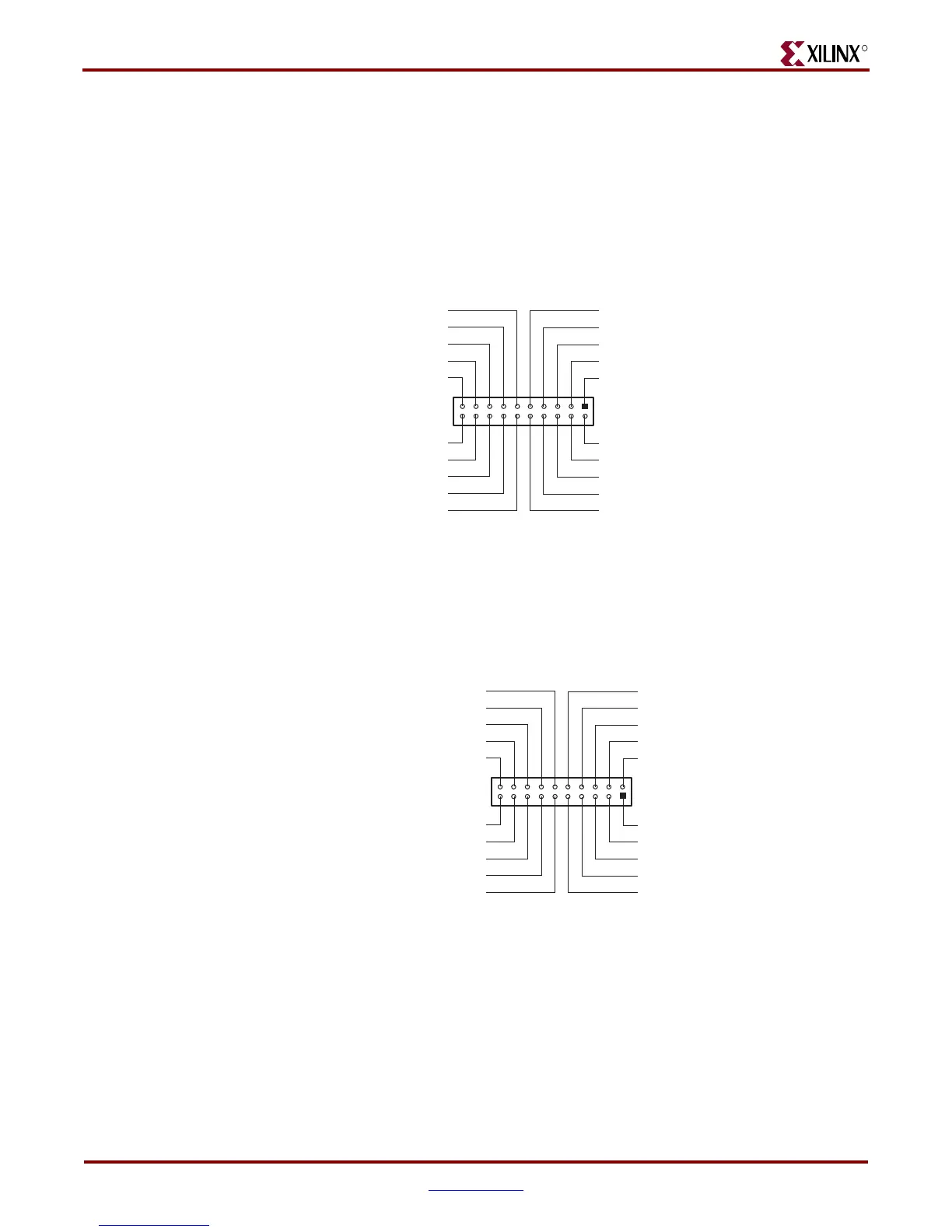
The upstream System ACE interface connector (P1) can be used to configure the DUT
(Figure 5). Any JTAG configuration stream can source this connector. For example, a
System ACE controller with a CompactFlash card can be used to generate very large JTAG
streams for configuring multiple Virtex-5 FPGA prototype platforms using the
downstream System ACE interface connector.
6b. Downstream System ACE Interface Connector
The downstream System ACE interface connector (P3) is used to pass configuration
information to a DUT in a downstream prototype platform board from sources such as a
Parallel Cable III cable or an upstream System ACE interface connector (Figure 6).
X-Ref Target - Figure 5
Figure 5: Upstream System ACE Interface Connector (20-Pin Female)
UG229_05_050407
NC
UPSTREAM_TMS
GND
UPSTREAM_TDI
GND
VCC_TMP
GND
UPSTREAM_TCK
GND
UPSTREAM_TDO
GND
VCC3_EN
VCC3_EN
VCC3_EN
VCC3_EN
VCC_TMP
VCC_TMP
VCC_TMP
VCC_TMP
GND
135791113151719
2468101214161820
X-Ref Target - Figure 6
Figure 6: Downstream System ACE Interface Connector (20-Pin Male)
UG229_06_050407
DOWNSTREAM_TDO
GND
DOWNSTREAM_TCK
GND
VCC_TMP
NC
DOWNSTREAM_TMS
GND
DOWNSTREAM_TDI
GND
GND
VCC_TMP
VCC_TMP
VCC_TMP
VCC_TMP
VCC3_EN
VCC3_EN
VCC3_EN
VCC3_EN
GND
135791113151719
2468101214161820