Zynq UltraScale+ VCU TRD User Guide 51
UG1250 (v2019.1) May 29, 2019 www.xilinx.com
Chapter 4: System Considerations
provides advanced management features instead of the PMU ROM. It then loads the first
stage boot loader (FSBL) into OCM and switches into tamper monitoring mode.
In this design, the FSBL is executed on APU-0. It initializes the PS and configures the PL and
APU based on the boot image header information. The following steps are performed:
1. The PL is configured with a bitstream and the PL reset is deasserted.
2. The Arm trusted firmware (ATF) is loaded into OCM and executed on APU-0.
3. The second stage boot loader U-Boot is loaded into DDR to be executed by APU-0.
Note:
At this point, RPU-1 is still held in reset because no executable has been loaded thus far.
For more information on the boot process, see chapters Programming View of Zynq
UltraScale+ MPSoC Devices and System Boot and Configuration in Zynq UltraScale+ MPSoC
Software Developer Guide (UG1137) [Ref 7], and chapter Boot and Configuration in Zynq
UltraScale+ MPSoC Technical Reference Manual (UG1085) [Ref 8].
Global Address Map
For more information on system addresses, see chapter 8 in Zynq UltraScale+ MPSoC
Technical Reference Manual (UG1085) [Ref 8].
Memory
The DMA instances in the PL use a 36-bit address space so they can access the DDR Low and
DDR High address regions for receiving and transmitting video buffers to be shared with
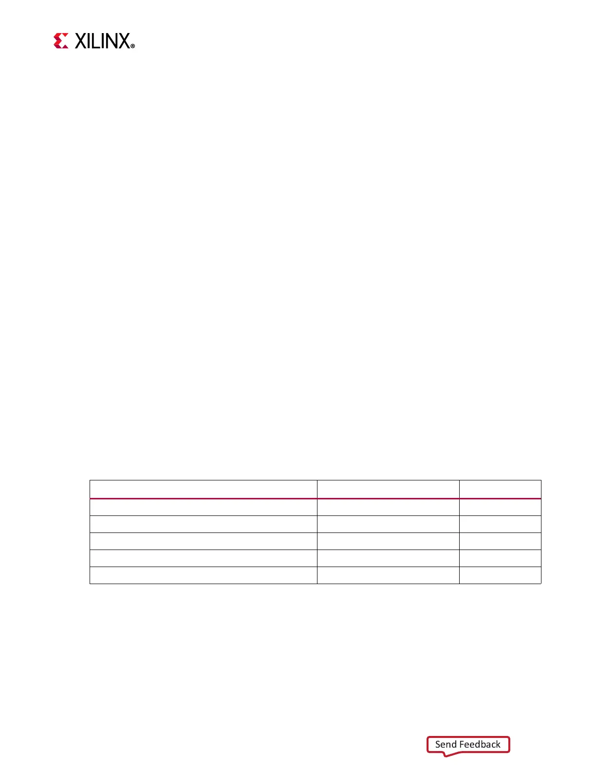
the APU application. Table 4- 1 lists the APU software components used in this design and
where they are stored or executed from in memory.
Video Buffer Format
The TRD uses two layers (or planes) for DisplayPort TX and up to eight layers for the HDMI
TX Subsystem. These layers get alpha-blended inside the display subsystem, which sends a
single video stream to the DisplayPort controller or HDMI Transmitter Subsystem. The
bottom layer is used for video frames and the top layer is used for graphics. The graphics
layer consists of the GUI and is rendered by the GPU. It overlays certain areas of the video
Table 4-1: Software Executables and Their Memory Regions
Component Processing Unit Memory
FSBL APU-0 OCM
Arm trusted firmware (ATF) APU-0 OCM
U-boot APU-0 DDR
Linux kernel/device tree/rootfs APU (SMP) DDR
vcu_qt application (Linux) APU (SMP) DDR
 Loading...