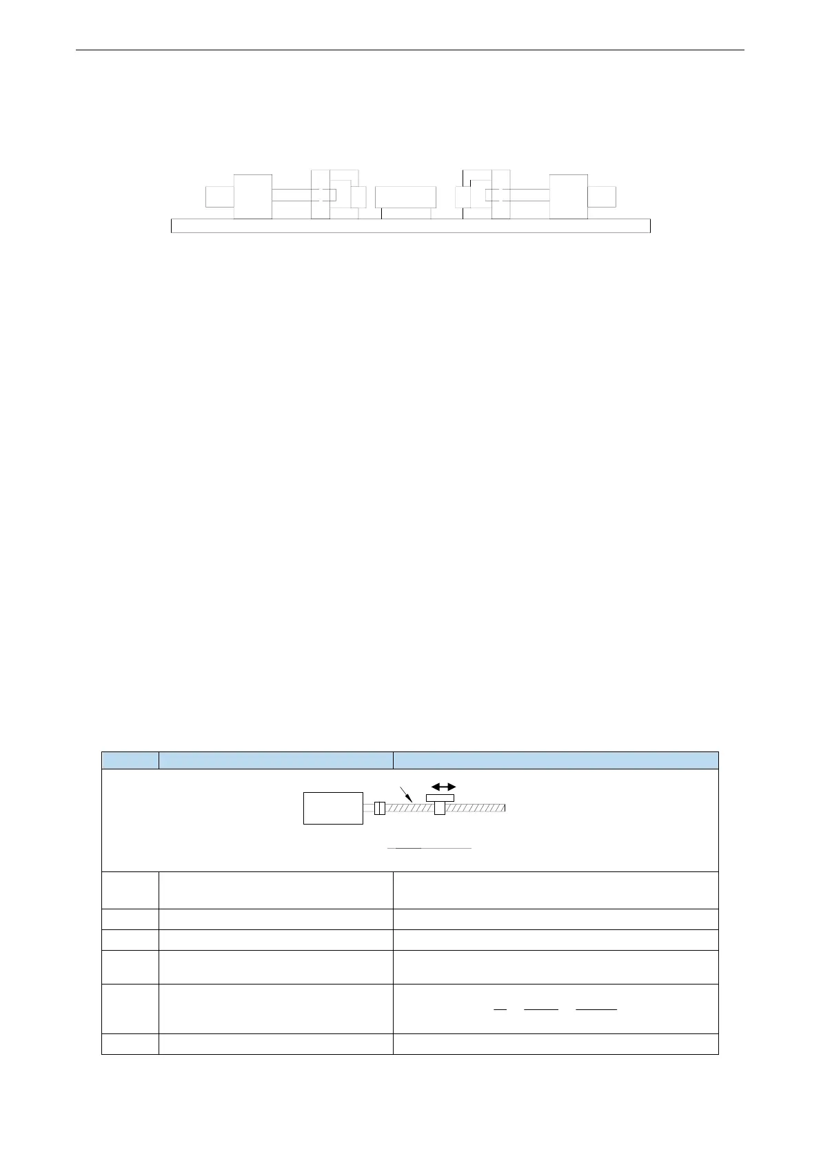
Equipment introduction:
This is a welder. Workpiece 1, 2, 3 are the object to be operated. 2 and 3 is fixed on B and A individually. A and
B can whole move and be pushed by ball screw E and F. The screw pitch is 5mm. C and D is servo motor. G and
H is reducer. The deceleration ratio is 40.
It needs to adjust the machine with standard dimension workpiece and find the origin of A and B.
Workpiece 1 lies on the worktable and moves left and right. Its dimension is positive tolerance, cannot shorter
than standard workpiece. The process to put the workpiece is random. It requires that the left and right soldering is
symmetrical.
A and B move toward 1 with 3 and 2 at the same speed. Whatever the position of 1, 2 or 3 will touch 1 at first and
push 1 to another side until 2 and 3 all touch 1. The result is the motor torque will increase. At this time, 1 will at
the symmetrical position.
A and B will return to the origin position after soldering is finished.
Analysis
1. Make sure the work mode: 6
2. It needs to judge whether 2 and 3 touch 1 when finding the symmetrical point first time. The sign is servo
output torque will increase. It needs to use torque limit (P3-28, P3-29) and torque limit output signal /CLT.
3. As the dimension of workpiece 1 is larger than standard, offset pulse will remain in servo when the symmetrical
point is found. /CLR signal can clear the pulse. The servo motor running distance is different from PLC pulse
number. If it needs to know the actual distance, servo encoder feedback /A+, /A-, /B+, /B- and AB phase count
are needed.
4. The machine motion direction of A and B.
Signal and terminal
/COIN positioning finished signal: SO1
/CLT torque up to upper limit output: SO2
/CLR pulse offset clear input: SI1
Encoder feedback signal /A+, /A-, /B+, /B-
Calculate the electronic gear ratio
 Loading...