V5 series inverter
96
Bit3: X4
Bit4: X5
Bit5: X6
Bit6: FWD
Bit7: REV
Bit8: OC
Bit9: relay output
Read data of function
code (03H)
GGnnH
(GG: Group No.
of function code nn:
function code No.)
Inverter responses to the data
(When use Modbus address, the nn must be turned into hex)
Write data to function
code (06H)
GGnnH
(GG: Group No.
of function code nn:
No. of function
code)
Write inverter data of function code (When use Modbus address,
the nn must be turned into hex)
Example:
Read function code P1.02:
01H, 03H, 01H, 02H, 00H, 01H, CRC1, CRC2
Read inverter setting frequency:
01H, 03H, 21H, 02H, 00H, 01H, CRC1, CRC2
Write function code P1.02, the write value is 1
01H, 06H, 01H, 02H, 00H, 01H, CRC1, CRC2
Running command:
01H, 06H, 20H, 00H, 00H, 01H, CRC1, CRC2
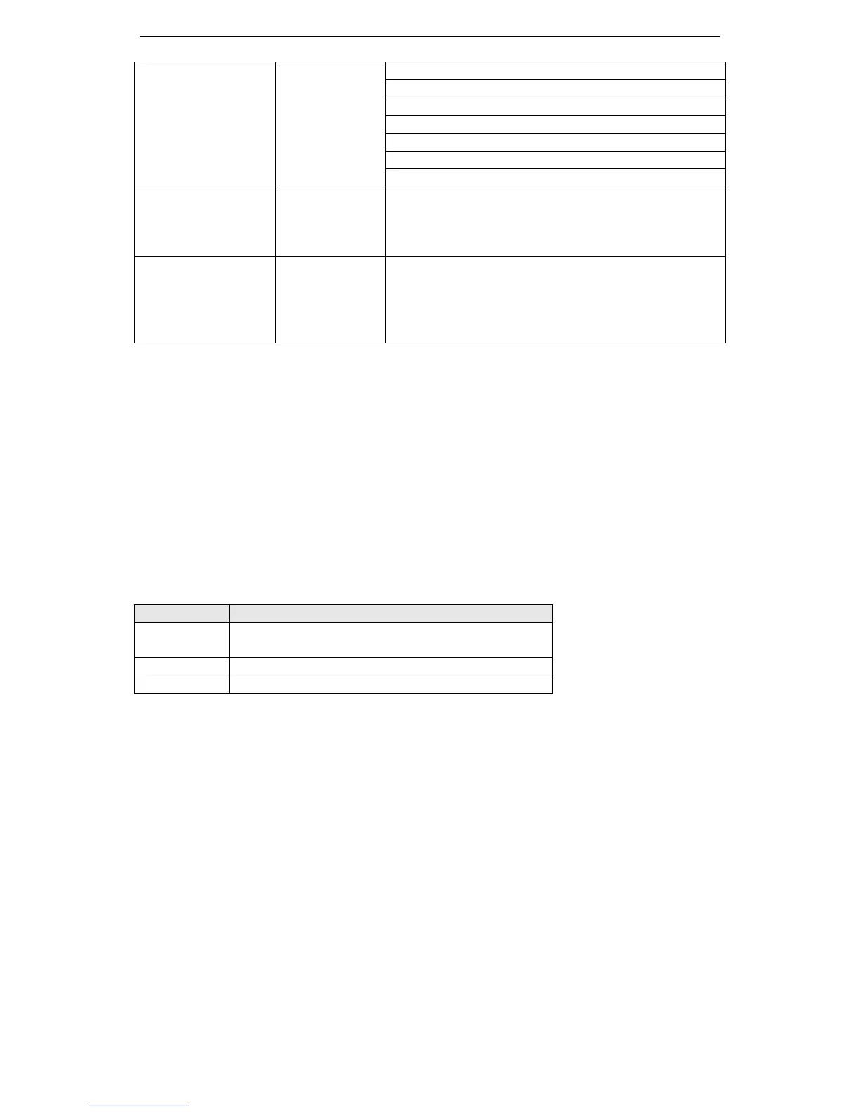
Definition of fault code:
Fault code Explanation
01H
Fault function code. Inverter can identify the function code:
03H, 06H, 08H
02H Error data address. Inverter cannot identify the data address
03H Error data. data over the limit
Note: The parameter address must in hex format, as the function codes of parameters are in decimal;
you have to transform them into hex. For example, the Modbus address of function code P2.11 is
020BH.