V5 series inverter
66
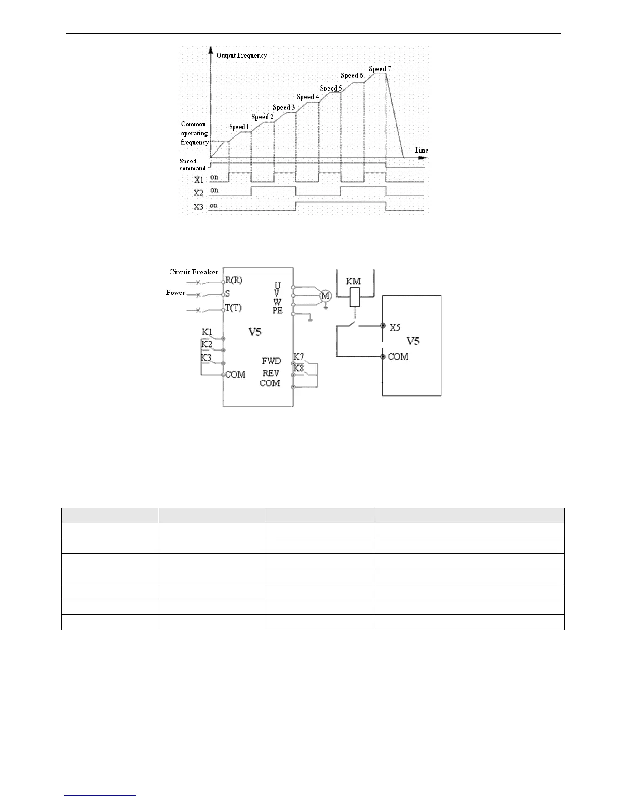
Fig.4-18 Multi-speed operation
In Fig.4-19 terminal control is selected, the running direction is controlled by K
7
, K
8
. In Fig.4-18, inverter can run at mul-
ti-speed 1~7 or normal speed by controlling the ON/OFF of K
1
, K
2
, K
3
.
Fig.4-19 Wire of multi-speed Fig.4-20 External device fault input
4~5: External jog input JOGP/JOGR. When choose terminal control (P0.03=1), JOGP is forward jog operation, JOGR
is reverse jog operation. Jog operating frequency and jog Acc/Dec time are defined in P3.06~P3.08.
6~8: Acc/Dec time selection
Table 4-3 Acc/Dec time selection
Terminal 3 Terminal 2 Terminal1 Acc/Dec time selection
OFF OFF OFF Acc time 1/Dec time 1
OFF OFF ON Acc time 2/ Dec time 2
OFF ON OFF Acc time 3/ Dec time 3
OFF ON ON Acc time 4/ Dec time 4
ON OFF OFF Acc time 5/ Dec time 5
ON OFF ON Acc time 6/ Dec time 6
ON ON OFF Acc time 7/ Dec time 7
Through the ON/OFF combination of the terminal, you can select acc/dec time 1~7.
9: 3-wire operation control. Refer to the introduction of P4.08.
10: Free stop(FRS). This function has the same meaning as the description in P2.05, while here it is controlled by ter-
minal controlling for remote application.
11: External stop command. This command is valid for all the running command channels and it can stop the inverter
according to the setting mode in P2.05.
12: DC braking command DB. DC brake the motor through the terminal in stop mode, to realize urgent stop or precision po-
sitioning. Brake starting frequency, brake current and time are defined in P2.06~P2.08. Brake time is the bigger one between
P2.07 and terminal lasting time.