V5 series inverter
69
Fig. 4-23 3-wire operation mode 1
Xi is the multi-function input terminal of X1~X6; here you should define its function to No.9 “3-wire control mode”.
3: 3-wire control mode 2
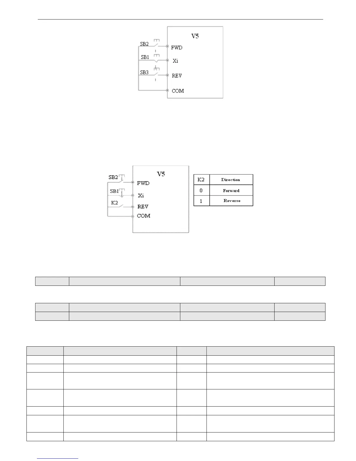
SB1: Stop button
SB2: Running button
Fig.4-24 3-wire control mode 2
Xi is the multi-function input terminal of X1~X6, here you should define its function to No.9 “3-wire control mode”.
Note: When the inverter alarming stop, if the running command channel is terminal and terminal FWD/REV is valid, in-
verter will reset the error and restart immediately.
P4.09 UP/DOWN speed rate Range: 0.01~99.99Hz/s 1.00 Hz/s
This parameter defines the changing rate of setting frequency changed by UP/DOWN terminal.
P4.10 Bi-direction open-collector output terminal OC Range: 0~20 0
P4.11 Relay output function selection Range: 0~20 15
Bi-direction open-collector output terminal OC, the options of this parameter are shown in Table 4-6.
Table 4-6 Functions of output terminals
Setting Functions Setting Functions
0 Inverter is running (RUN) 11 PLC one period running is completed
1 Frequency arriving signal (FAR) 12 Reach the setting counter value
2 Frequency level detection signal (FDT1) 13
Reach the middle counter value
3 Frequency level detection signal (FDT2) 14 Inverter running preparation finished (RDY)
4 Overload pre-alarm (OL) 15 Inverter fault
5 Inverter under voltage locking (LU) 16 Running at start frequency
6 External fault stop (EXT) 17 DC braking when startup