V5 series inverter
82
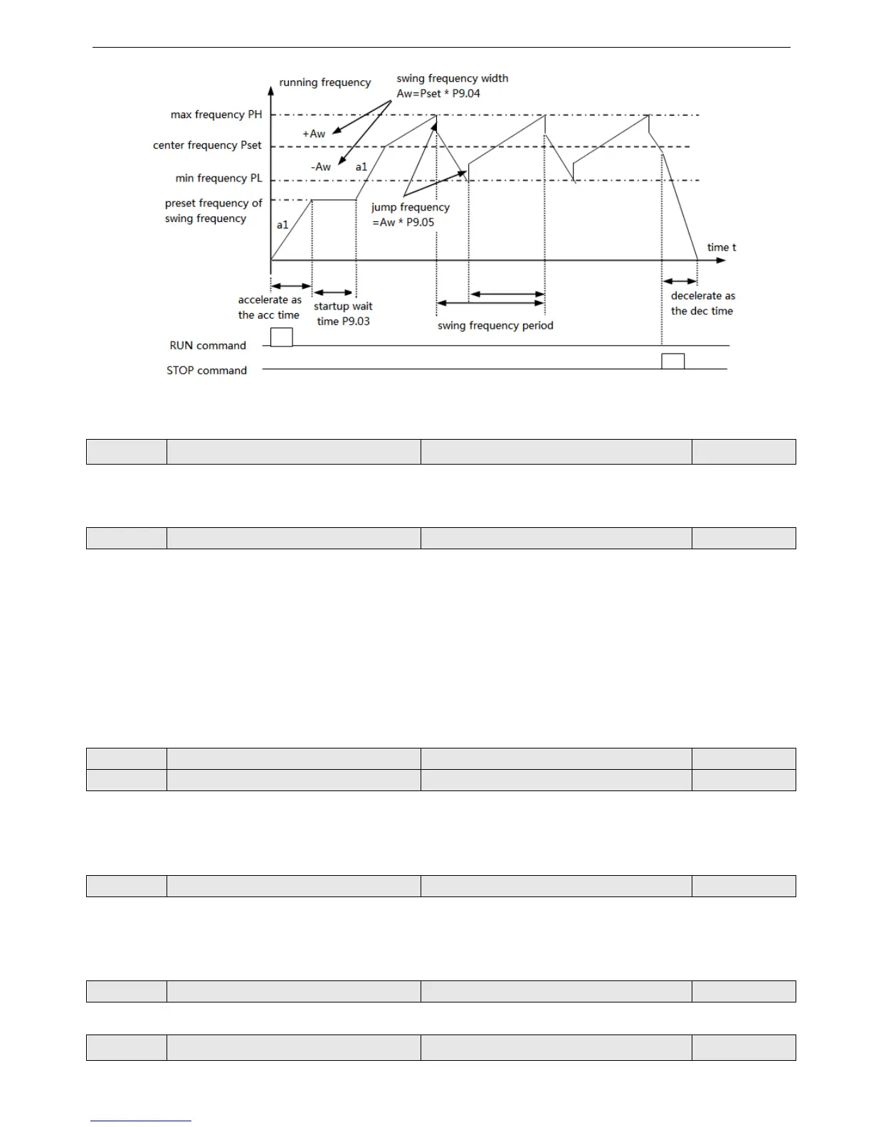
Fig.4-45 swing frequency
P9.00 Swing frequency function Range: 0, 1 0
0: Disabled
1: Enabled
P9.01 Swing frequency running mode Range: 00~11 0
Lowest bit of LED:input mode
0: Auto input mode. The inverter will run at preset frequency (P9.02) for a while (P9.03), and then enter the swing fre-
quency status.
1: Terminal manual input mode. If the multi-function terminal (Xi is set to No.25 function) is enabled, the inverter will
enter swing frequency status. If the terminal is disabled, the inverter will quit swing frequency and run at preset swing fre-
quency (P9.02).
Ten bit of LED: swing frequency width
0: Variable width. Width AW changes with the center frequency and the changing rate is defined by P9.04.
1: Fixed width. Width AW is decided by max frequency and P9.04.
P9.02 Preset swing frequency Range: 0.00~650.00Hz 0.00Hz
P9.03 Waiting time of preset swing frequency Range: 0.0~6000.0s 0.0s
P9.02 is used to set running frequency before entering swing frequency.
If you select auto start mode, P9.03 is used to set the running lasting time at preset swing frequency before the inverter
enter swing frequency; if you select manual start mode, P9.03 is disabled. Refer to Fig. 4-45.
P9.04 The width of swing frequency Range: 0.0~50.0% 0.0%
Variable width: Aw=Center frequency×P9.04
Fixed width: Aw=Max running frequency P0.06×P9.04
Prompt: The swing frequency is limited by upper/lower frequency, it will work abnormal if set uncorrect.
P9.05 Jump frequency Range: 0.0~50.0% 0.0%
As shown in Fig4-45, there is no jump frequency if P9.05 = 0.
P9.06 Swing frequency period Range: 0.1~999.9s 10.0s
It defines the complete period of swing frequency up/down process.