VB5N series inverter
63
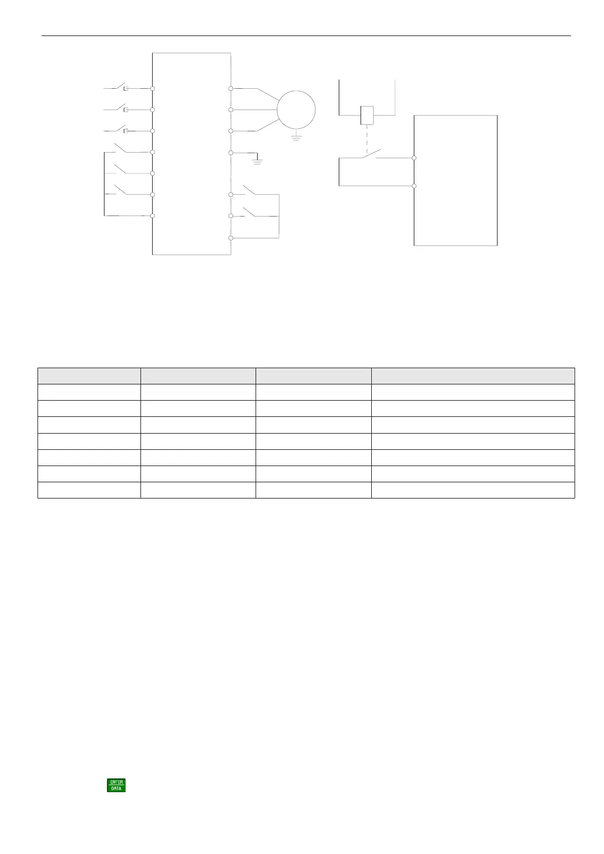
Fig.4-19 Wire of multi-speed Fig.4-20 External device fault input
4~5: External jog input JOGP/JOGR. When choose terminal control (P0.03=1), JOGP is forward jog operation, JOGR
is reverse jog operation. Jog operating frequency and jog Acc/Dec time are defined in P3.06~P3.08.
6~8: Acc/Dec time selection
Table 4-3 Acc/Dec time selection
Through the ON/OFF combination of the terminal, you can select acc/dec time 1~7.
9: 3-wire operation control. Refer to the introduction of P4.08.
10: Free stop(FRS). This function has the same meaning as the description in P2.05, while here it is controlled by ter-
minal controlling for remote application.
11: External stop command. This command is valid for all the running command channels and it can stop the inverter
according to the setting mode in P2.05.
12: DC braking command DB. DC brake the motor through the terminal in stop mode, to realize urgent stop or precision po-
sitioning. Brake starting frequency, brake current and time are defined in P2.06~P2.08. Brake time is the bigger one between
P2.07 and terminal lasting time.
13: Inverter running prohibition. When the terminal is enabled, the inverter will free stop in running mode and prohibit to
restart in standby mode. This function is sutiable for safe linkage.
14~15: Frequency up (UP)/Frequency down (DOWN). The terminal can be used to increase or decrease the frequency.
Its function is the same with operating keys on the panel, easy for remote control. This terminal is enabled when P0.01=3.
Increase or decrease rate is determined by P4.09.
16: Acc/Dec prohibition. The terminal can make the motor keep current speed without being influenced by external signal.
It is invalid when normal decelerate stop.
17: External reset signal. The inverter can be reset via this terminal when the inverter has a fault. The function of this terminal
is the same to on the panel.
18: External fault signal input. The fault signal of external equipment can be input via the terminal, which is convenient
for the inverter to monitor the external equipment. Once the inverter receives the fault signal, it will display “E-13”. Refer
 Loading...