VB5N series inverter
64
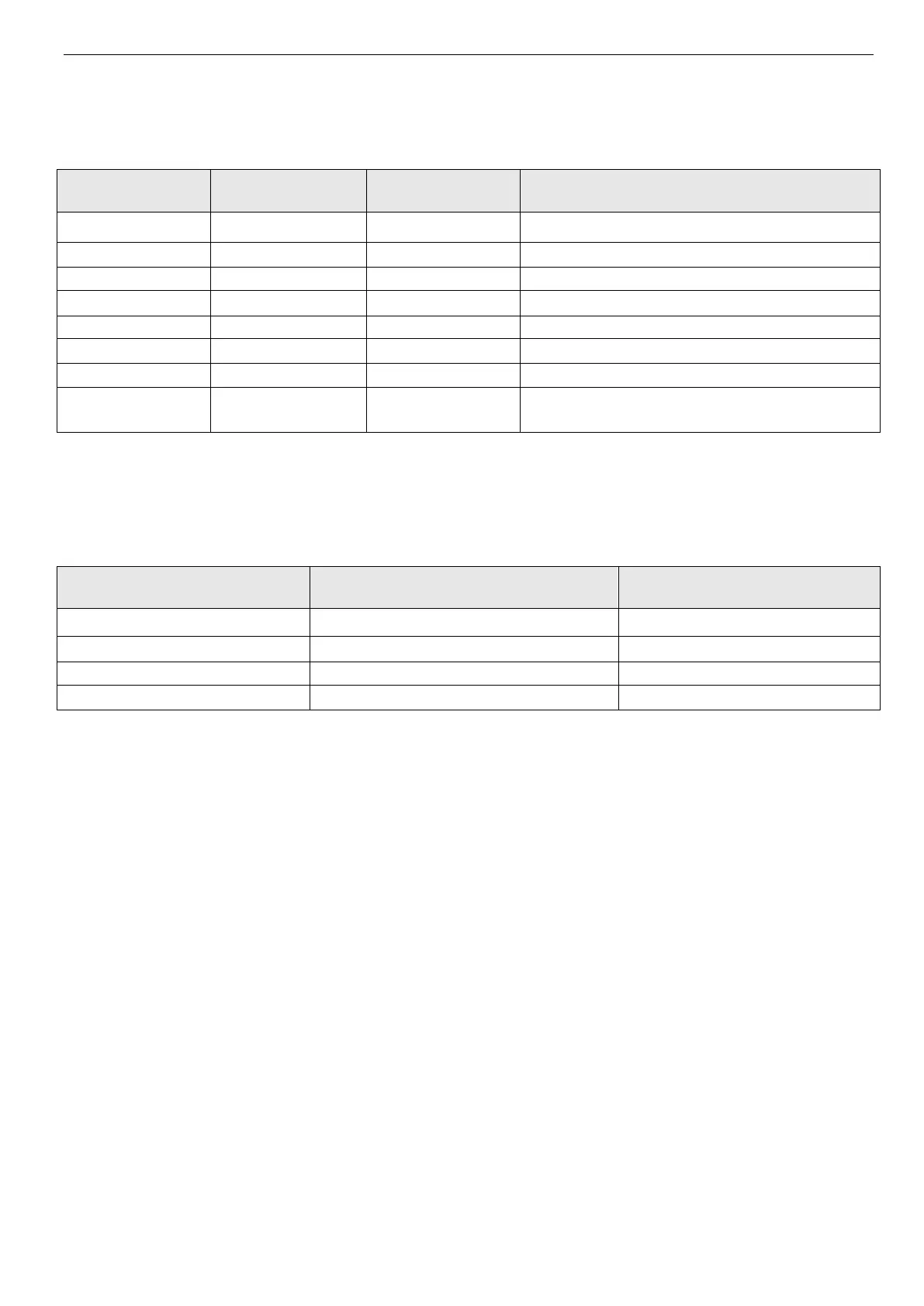
to Fig.4-20.
19~21: Frequency setting channel 1. Different ON/OFF combination of terminals 19, 20 and 21 can select frequency as
shown in Table 4-4. The priority of terminal setting and function code P0.01 setting: the final setting is valid.
Table 4-4 Frequency selection
Frequency setting
terminal 3
Frequency setting
terminal 2
Frequency setting
terminal 1
Frequency setting channel
Keep the frequency setting
Combination setting
(refer to P3.01)
22: Command switch to the terminal.When this terminal is enabled, the running command channel will switch to termi-
nal command channel.
23~24: Select the comman channel by terminal. Select the command channel by terminal ON/OFF combination. Please
see table 4-5. The priority of terminal and P0.03: the final setting is valid.
Table 4-5 running command channel
Keep running command channel
Serial port command channel
25: Swing frequency input. When the swing frequency mode is manual input, the swing frequency function is valid when
this terminal is valid, refer to the introductions of P9.
26: Reset swing frequency. No matter the swing frequency mode is “Manual” or “Auto”, when this terminal is ON, the
status of swing frequency in the inverter will be cleared. Disconncet this terminal can restart the swing frequency. Refer to
P9.
27: Close-loop disabled. Switch between the close-loop operation and low level operation. When switching to low level
operation mode, start/stop, direction and acc/dec time are accord to the setting of related running mode.
Note: Switching between close-loop operation and low level operation can be realized only when close-loop is enabled
(P7.00 =1).
28: Pause the PLC operation. Pause the running PLC. Inverter run at 0 frequency when this terminal is valid, PLC run-
ning time is not counted. When the terminal is invalid, PLC will auto-track the speed and continue to run. Please refer to
P8.
29: PLC disabled. This terminal can be used to flexible switch the PLC operation and low level operation.
Note: The switching between PLC operation and low level operation are valid only when PLC is running (the lowest bit of
P8.00 is not 0)
30: Reset PLC stopping status. When PLC is in stopping status, the enabled terminal can clear PLC running stage, run-
ning time, running frequency and other informations of PLC stopping memory. Refer to P8 for instructions.
31: Frequency switches to CI. The frequency setting channel switches to CI when this terminal is valid. If it is invalid, the
frequency setting channel will restore.
32: Counter trigger signal input. Counter pulse input of internal counter, the max frequency is 200Hz. The count value is
latched. Refer to P4.21, P4.22.
33: Counter reset input. Reset the internal counter of inverter. Use with function No.32 (counter trigger signal input).
34: External interrupt input. After receiving external interrupt input signal, inverter will lock output and run at 0 Hz,
 Loading...