VB5N series inverter
77
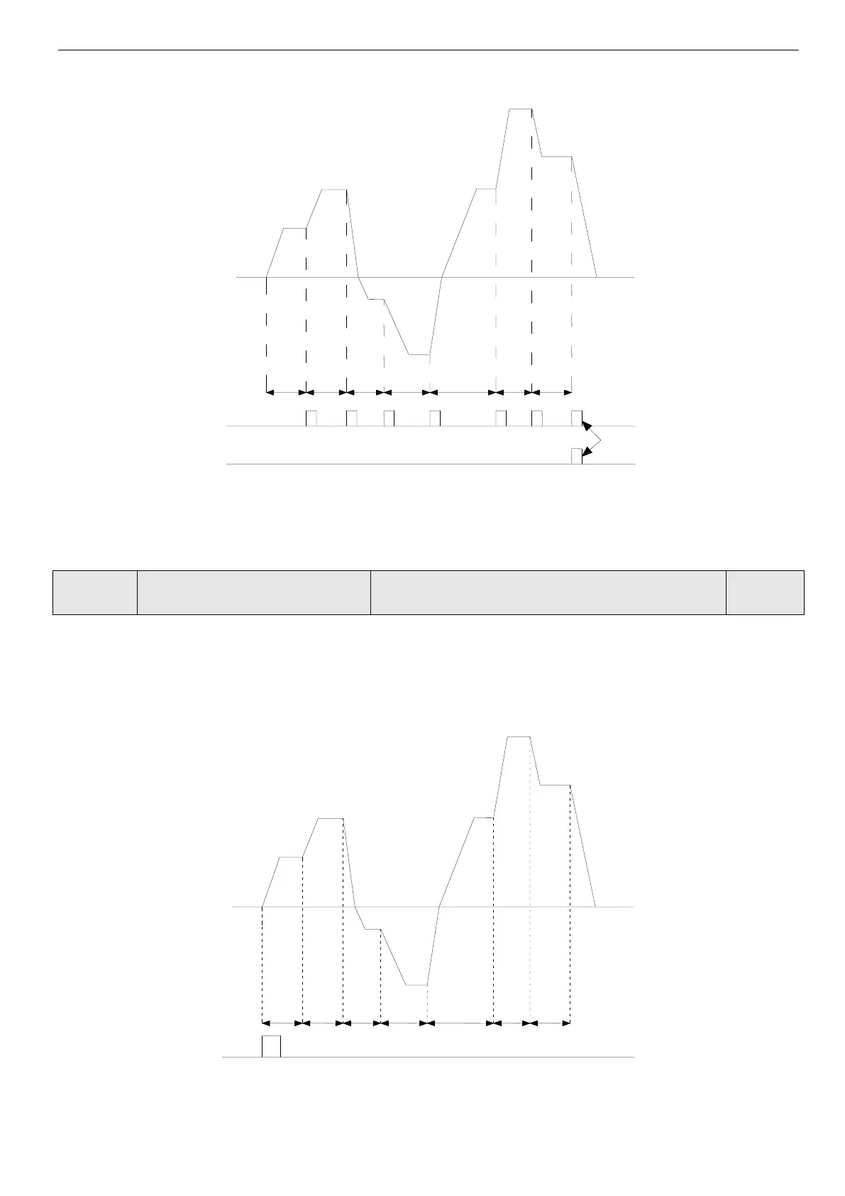
Fig.4-40 Simple PLC running
In Fig 4-40, a
1
~a
7
, d
1
~d
7
are the Acc/Dec time of each stage and they are set by Acc/Dec time parameters P0.17, P0.18 and
P3.14~P3.2. F
1
~F
7
, T
1
~T
7
are the running frequency and running time and they are set by P8.01~P8.14.
Range: LED lowest bit: 0~3; ten bit: 0, 1; hundred bit: 0, 1;
Lowest bit of LED: PLC running mode selection
0: Disabled. PLC running mode is invalid.
1: Stop after one cycle. As shown in Fig.4-41. If inverter stops after single cycle operation, running command should be
input once again to start the inverter.
Fig. 4-41 PLC stop mode after single cycle
2: Keep the final value after single cycle. As shown in Fig.4-42, Inverter will keep the running frequency, direction of the
last stage after single cycle is completed, then it will stop in dec time if stop command is input.
Indication of PLC stage finished
Indication of PLC cycle finished
 Loading...