Do you have a question about the XP GLASSMAN EJ Series and is the answer not in the manual?
Details the warranty terms, exclusions, and buyer remedies for XP Power supplies.
Procedures for inspecting packages and equipment for damage upon receipt.
Guidelines for contacting XP Glassman and listing included accessories.
Explains hazard symbols, defined terms (CAUTION, WARNING), and general safety precautions.
Information on maintenance, user-replaceable parts (fuses), and warnings.
Identifies and describes rear panel connectors and switches for power input and interfaces.
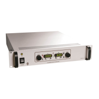
Details front panel components including switches, indicators, and hardware for installation.
Detailed description of front panel pushbuttons and encoders for voltage, current, and mode selection.
Explanation of LEDs indicating status and digital meters for voltage/current display.
Operation of the STANDBY button and the CONTROL LOCK feature for preventing accidental changes.
Recommendations for rack mounting, bench-top use, and essential safety precautions during installation.
Step-by-step guide for connecting and powering on the unit for local or remote control.
Instructions for interchanging HV modules to reverse polarity in specific FR/FJ and EJ/ET/EY models.
Steps to interchange HV modules for FJ/FR models with 5kV or lower ratings.
Procedure to change polarity using a polarity card in EJ/ET/EY models up to 6kV.
Details on analog signal inputs for programming voltage, current, HV enable, and status monitoring.
Describes RS232, USB, and Ethernet interfaces for remote control and monitoring via computer.
Defines the structure and byte content for setting power supply parameters via ASCII commands.
Details the command for requesting power supply status information and its response format.
Explains error codes and messages returned for communication or command errors.
| Input Voltage | 100-240V AC |
|---|---|
| Polarity | Positive |
| Regulation - Line | ±0.01% |
| Operating Temperature | 0°C to 40°C |
| Storage Temperature | -20°C to 70°C |
| Protection | Overvoltage, Overcurrent |
| Voltage Regulation | ±0.01% |
| Storage Temperature Range | -20°C to 70°C |
| Dimensions | 4.0" H x 4.0" W x 7.0" D (101.6 mm x 101.6 mm x 177.8 mm) |