Series EJ, ET, EY, FJ & FR
102002-177 Rev M2
15
\1020\02177M2.doc 17 Jun 2019
ELEMENT DEVICE
TYPE
FUNCTION DESCRIPTION
18 HV ON LED Red
Indicator
LED indicates HV ON
function is enabled.
HV ON LED indicates that the Interlock is
closed and the HV ON button has been
pressed (or Remote HV ON pins on J3 have
been connected). HV Enable is a separate
function, and must also be enabled in order
to produce HV.
19 CONTROL
LOCK
LED Yellow
(Amber)
Indicator
LED indicates Control Lock
is active.
20 POLARITY
LED Green
Indicators
LEDs indicate polarity of the
HV output.
These are always functional as long as the
AC power switch is ON.
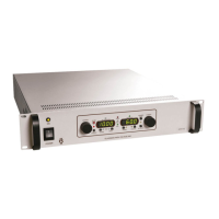
Output Meters
3-1/2 digit digital meters display output voltage and current (1250 count maximum).
WARNING! When system is powered down under light or no load conditions, the
output may retain a charge even after power is removed. This charge may not show on
the voltage meter. Discharge the output to ground or use an external meter to
determine if output has discharged. Or, wait at least 15 seconds before making or
removing any connections to the supply.

 Loading...