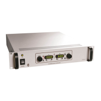
Series EJ, ET, EY, FJ & FR
102002-177 Rev M2
14
\1020\02177M2.doc 17 Jun 2019
ELEMENT DEVICE
TYPE
FUNCTION DESCRIPTION
8 ENABLE
REM/LOC
Momentary
Pushbutton;
Toggle
Toggles HV Enable (TTL)
signal from local to remote
and lights LED. (Item 16)
In local mode, HV is always enabled. Remote
is analog by default. Connecting a computer
running control software while in remote
Enable will switch control from remote analog
to remote digital automatically.
9 PROGRAM
REM/LOC
Momentary
Pushbutton;
Toggle
Switches the voltage and
current programs between
local and remote operation
and lights LED. (Item 14)
Remote is analog by default. Connecting a
computer running control software while in
remote Program will switch control from
remote analog to remote digital automatically.
10 STANDBY
Momentary
Pushbutton
Places unit in Standby
Mode. Turns off HV output
and HV ON LED. (Item 18)
Resets Current Trip and Arc Latch (Optional)
11 VOLTAGE LED
Green
Indicator
LED indicates Voltage
Mode
The output is controlled as voltage by the
Voltage Encoder or remote voltage program.
12 CURRENT LED
Green
Indicator
LED indicates Current
Mode
The output is controlled as current by the
Current Encoder or remote current program.
13 FAULT LED
Red Indicator
LED indicates an active
FAULT
Output shuts down for any of: OT, AC input
under voltage, and fan failure. LED lit signals
fault.
14 PROGRAM
REM/LOC
LED Green
Indicator
LED indicates Remote
Programming
Remote is analog by default. Connecting a
computer running control software while in
remote Program will switch control from
remote analog to remote digital automatically.
15 PRESET LED Yellow
(Amber)
Indicator
LED indicates PRESET
Mode
16 ENABLE
REM/LOC
LED Green
Indicator
LED indicates Remote
Enable
Remote is analog by default. Connecting a
computer running control software while in
remote Enable will switch control from remote
analog to remote digital automatically.
17 FINE ADJ. LED Yellow
(Amber)
Indicator
LED indicates FINE
adjustment mode

 Loading...