10
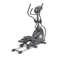
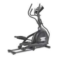
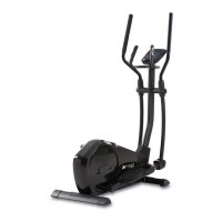
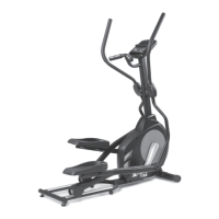
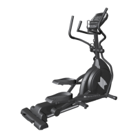
FS4.0e Elliptical
#115. M5 x 15mm
Phillips Head Screw
(14 pcs)
#119. 3.5 x 12mm
Sheet Metal Screw
(8 pcs)
#122. M6 x 10mm
Phillips Head Screw
(4 pcs)
4
Hardware Step 4
1. Secure the roller wheel covers (52) over the roller wheels with two
Phillips Head Screws (79). Secure the Left (59) and Right (60) Lower
Swing Arm Covers to the right connecting arm/lower right swing arm con-
nection with two Phillips Head Screws (79) and one Self Taping Screw
(84). Repeat this process on the left side.
2. Fit the Front (56) and Back (57) Handle Bar Covers into place over the
swing arm axle joint. Secure with three Self Taping Screws (84). Repeat
this process on the left side with the left Handle Bar Covers (54 & 55).
3. Plug the wire from the power supply into the outlet on the front left side
of the elliptical trainer and the other end into the wall outlet. The unit is
now ready for use.
Plastic Covers
Note: Use the M5 Allen Wrench/Phillips Head Screw Driver (108) to tighten hardware in this step.
 Loading...