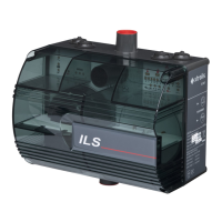
ICAM by Xtralis ICAM ILS-2 Product Guide
www.xtralis.com 11
4 Pipe Installation
A simple guide to pipe installation follows with examples of standard configurations.
Note: ASPIRE may be downloaded from www.xtralis.com and should be used to calculate transport
times, dilution effects etc. for all installations beyond the scope of this guide.
Use 25 mm (or ¾”) Red ABS pipe with sampling point holes drilled along its length. The pipe run is terminated
with an end cap that has a hole drilled in its center.
The position of each individual sampling point should adhere to guidelines for positioning point detectors. It is
important to note that the smoke concentration from an individual sampling point will be diluted by the clean air
from the other sample points and the end cap hole.
The ILS-2 inlet ports are tapered to allow a push fit of the sampling pipe. The pipe should be cut squarely to
ensure a good, airtight seal. Solvent adhesive should not be used for this joint.
Use pipe cutting shears or a wheel type plastic tube cutter to cut pipes to the required length as per the
sampling network design. Ensure that cuts are square.
4.1 Pipe Specification
For EN54-20 compliance, the pipe should be Red ABS to EN 50086-1 (Crush 1, Impact 1, Temp 31) with a
nominal outer diameter of 25 mm (or ¾”). The sampling pipe is normally supplied in 3 m lengths and is cut as
required and joined by solvent welded sockets (permanent), or socket unions (removable).
4.2 Fixings
The normal fixing methods are pipe clips, saddle clamps or even tie wraps. Fixing centers are typically 1.5 m
apart.
4.3 Bends
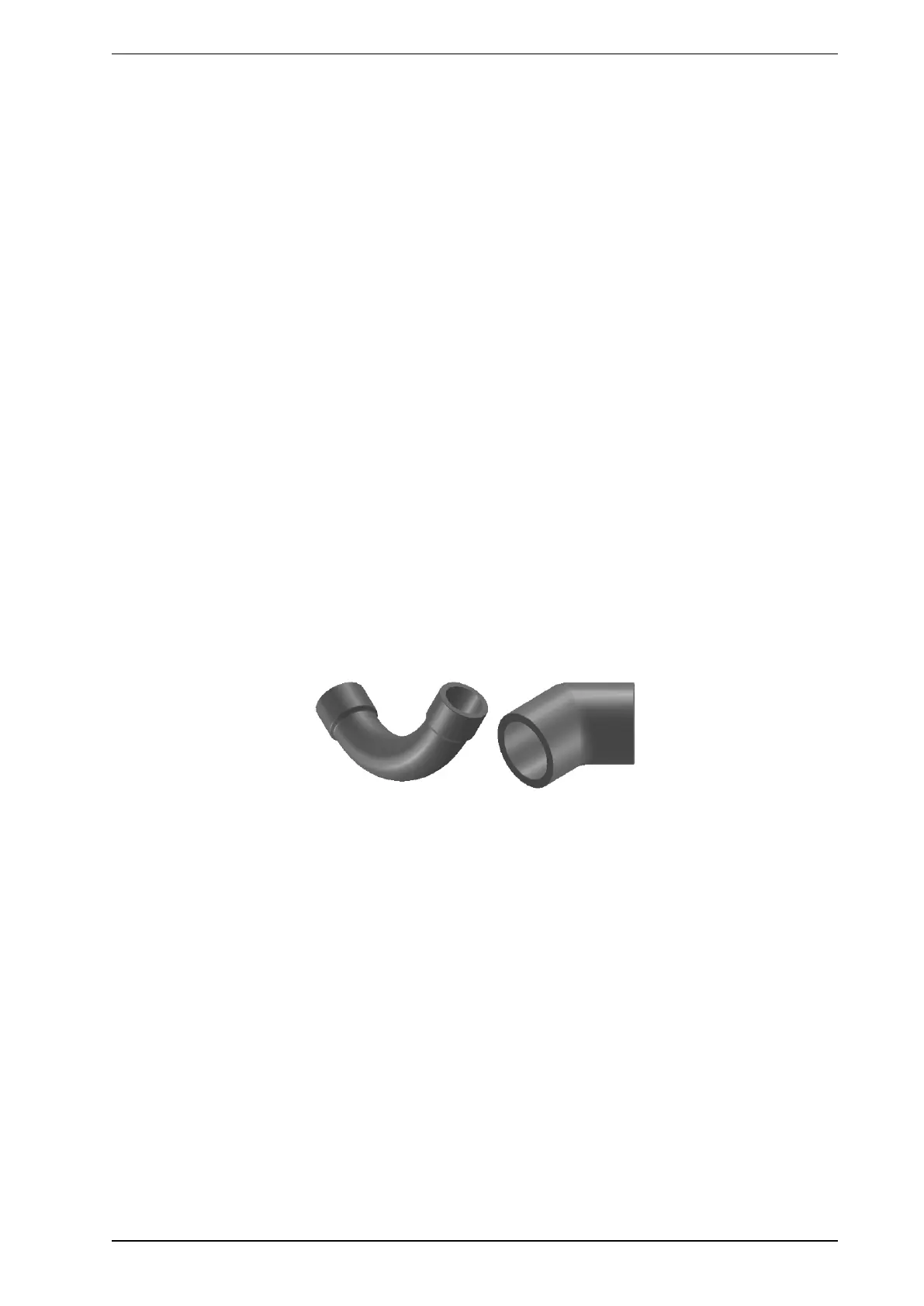
Figure 4-1: 45° bend and 90° swept bend
Bends are either 45° or 90°. For 90° bends it is very important that swept bends are used and not sharp
elbows, as sharp elbows introduce unacceptable pressure losses and significantly increase the response
times from holes beyond the bend.
 Loading...