19
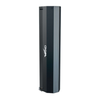
3.8.3. Venting (discharge) valve
- Water exchangers are fitted with venting screws on the inlet and drainage collectors.
- Venting of the exchanger is done by loosening the vent screw.
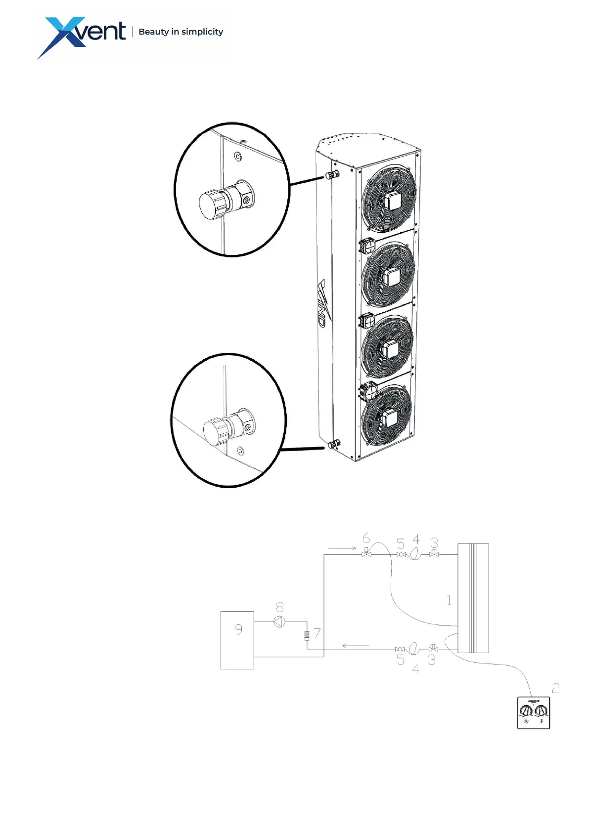
3.8.4. Example hydraulic diagram of unit connection
- If the automatic control valve is not installed to control the heating capacity, we recommend to shut off the
heating water supply to the exchanger when the fan is switched off. Any high temperature inside the unit on
the exchanger may reduce the fan lifespan.
1. Wind
2. speed regulator with thermostat
3. vent valve - part of the exchanger
4. flexible hose
5. shut-off valve
6. 2-way valve with thermoelectric drive
7. filter
8. pump
9. source of hot water
 Loading...