21
- If it is necessary to remove the wire from the terminal, press the orange locking button located on the
terminal using a suitable tool and then pull the wire out of the terminal accordingly.
- The optimum cross-section of the conductor must be selected according to the actual length of the conductor
route; however, the cross-section of the conductor may be max. 1,5 mm
2
.
- All wires must be connected to terminals with a reasonable force to prevent their damage. Stripping of
cables to individual conductors should be 10mm. In the case of strand-type conductors, an end piece
must be pressed on (tube).
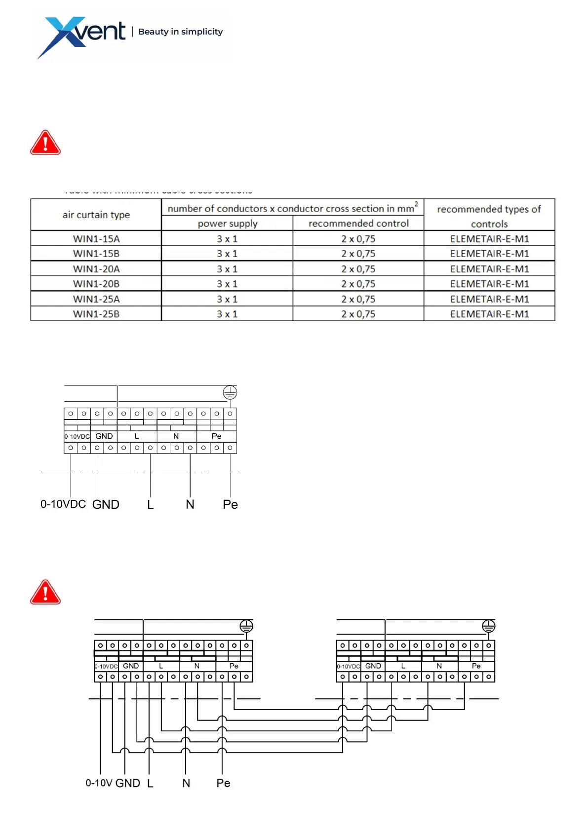
- Table with minimum cable cross sections
3.9.3. Description of power and control terminals – electrical diagram of motors
3.9.3.1. Description of connection of 1 curtain
3.9.3.2. Description of the curtain connection during the chaining
- Connect the curtains during the chaining according to the diagram, see point 5.3.
- The connecting terminals allow inter-connection of the chained curtains. However, up to a maximum total
current 15 A of the entire chain assembly, and the maximum cross-section of the conductors of 1.5 mm2.
- The earthing conductor must be connected separately. It is not possible to chain through the connecting
terminals.
Clamps intended for power supply
- Terminal marked as L – supply phase.
- Terminal marked as N – neutral conductor.
- Green-yellow terminal marked as Pe – grounding wire
- Terminals intended for control
- Terminal marked as PWM/0-10V – input control signal 0-10V
- Terminal marked GND – input special grounding wire to the
fan control signal. It shall not be used otherwise than to
control the fan.
air curtain Wind
air curtain Wind 1
air curtain Wind 2
 Loading...