• Recommended rough cut feed rate per revolution is 0.008 in. (0.20 mm) and depth of
cut is 0.050 in (1.27 mm).
• Recommended finish cut feed rate per revolution is 0.015 in. (0.38 mm) and depth of
cut is 0.010 in (0.25 mm).
Balancing
It is recommended that impellers trimmed more than 5% in diameter be rebalanced per
ISO 1940 grade G6.3.
Angle cut guidelines
Model e-1510-4AD pump impellers must be angle cut at reduced diameters according to
the following information.
Figure 6: 4AD impeller trim — 0.125 in. (3.17 mm) increments
A B C
Hydraulic diameter, nominal, as
shown on selection curves
Diameter at impeller inlet side
shroud
Trim angle
From maximum diameter 7 in.
(177.8 mm) to 6.125 in. (155.6 mm)
Use diameter from selection curves 0 degrees, no angle
6, 5.875, 5.75, 5.625 in. (162.4 to
142.9 mm)
B = A plus 0.250 in. (6.35 mm) 8 degrees
5.5, 5.375, 5.25, 5.125, minimum 5
in. (139.7 to 127.0 mm)
B = A plus 0.375 in. (9.53 mm) 8 degrees
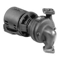
6.4 Reassembly
6.4.1 Seal assembly
6.4.1.1 Assemble the standard mechanical seal (e-1510 and e-1510-F)
1. Lubricate the shaft sleeve and coverplate seal cavity with soapy water.
Do not use a petroleum lubricant.
2. Install a new insert gasket.
3. Install a new seal insert and make sure that the indentation is against the insert gasket.
4. Slide a new rotating seal assembly onto the shaft sleeve.
5. Push the top of the compression ring with a screwdriver until the seal is tight against
the seal insert.
6. Install the seal spring and point the narrow end toward the seal.
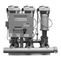
6 Maintenance
Series e-1510 INSTRUCTION MANUAL 29
 Loading...