10 FT-60R/E Technical Supplement
Alignment
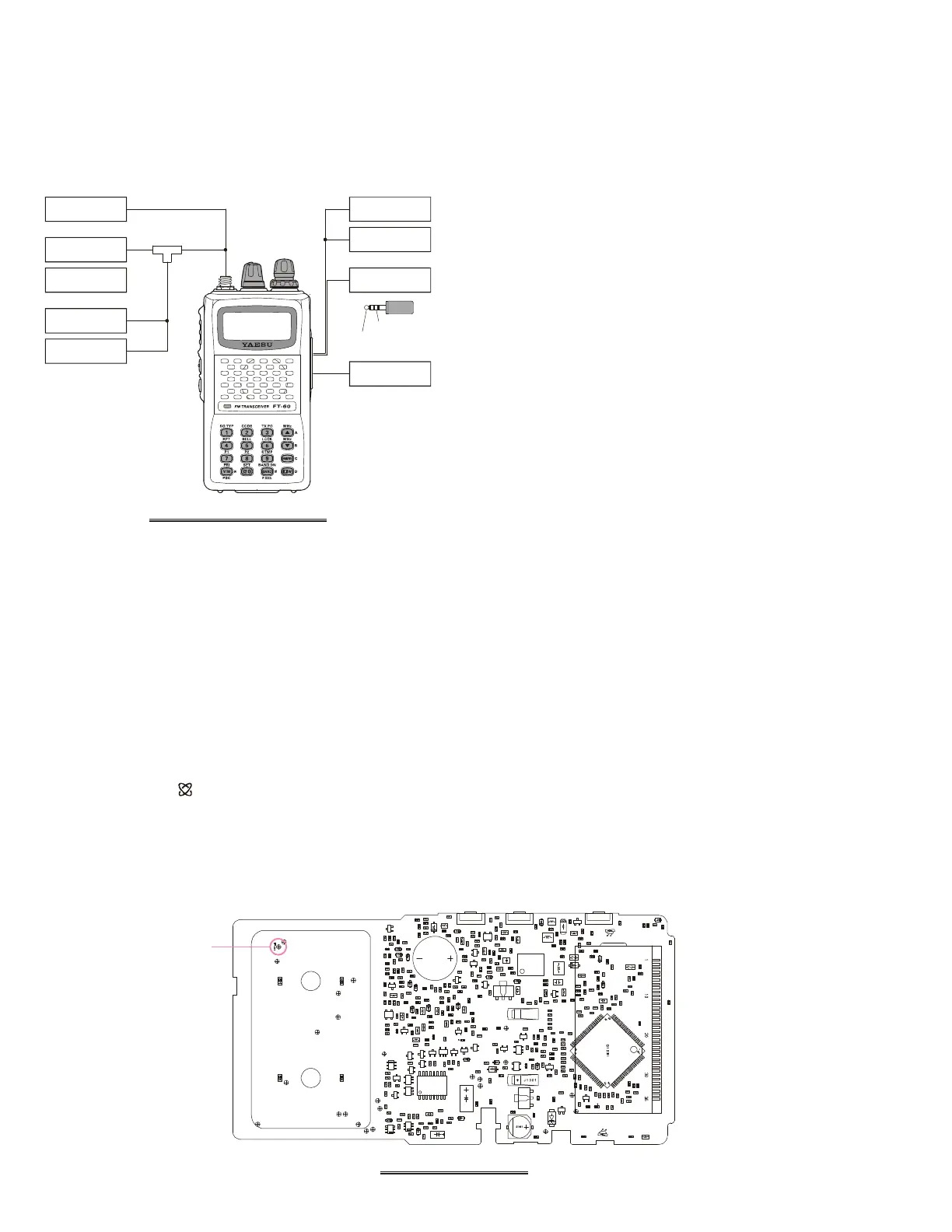
Test Setup
Set up the test equipment as shown below for transceiver
alignment, and apply 9.9 V DC power to the transceiver.
Refer to the drawings for Alignment Points.
PLL Reference Frequency
1. Tune the frequency to 435.050 MHz, then set the trans-
mit power level to “LOW.”
2. Press the
[
F/W
]
key, then press the
[
BAND
(
BAND DN
)]
key to set the alignment parameter to “
A0 REF.xxxA0 REF.xxx
A0 REF.xxxA0 REF.xxx
A0 REF.xxx,” if
needed.
3. With in five second of appearing the “
A0 REF.xxxA0 REF.xxx
A0 REF.xxxA0 REF.xxx
A0 REF.xxx” on
the display, press the PTT switch to activate the trans-
mitter, adjust the DIAL knob so that the counter fre-
quency reading is 435.050 MHz (±100 Hz).
RF Front-end Tuning
1. Connect the DC voltmeter to TP1015 on the MAIN
unit, then inject a 439.050 MHz signal at a level of +10
dBμ (with 1 kHz modulation @±3.5 kHz deviation)
from the RF signal generator.
2. Tune the frequency to 439.050 MHz.
3. Press the
[
F/W
]
key, then press the
[
BAND
(
BAND DN
)]
key to set the alignment parameter to “
A1 TUN.xxxA1 TUN.xxx
A1 TUN.xxxA1 TUN.xxx
A1 TUN.xxx.”
4. With in five second of appearing the “
A1 TUN.xxxA1 TUN.xxx
A1 TUN.xxxA1 TUN.xxx
A1 TUN.xxx” on
the display, adjust the DIAL knob so that the DC volt-
meter reaches maximum deflection. The FT-60R/E’s RF
Front-end has a broad bandwidth. Therefore, prior to
adjustment you must adjust the DIAL knob to set the
frequency to the middle of the band, in step 2, so you
can set peak in the DC voltmeter’s deflection in the
center of the RF passband.
5. Tune the frequency to 145.050 MHz.
6. Inject a 145.050 MHz signal at a level of +10 dBμ (with
1 kHz modulation @±3.5 kHz deviation) from the RF
signal generator.
7. Press the
[
F/W
]
key to recall the alignment parameter
to “
A1 TUN.xxxA1 TUN.xxx
A1 TUN.xxxA1 TUN.xxx
A1 TUN.xxx.”
8. With in five second of appearing the “
A1 TUN.xxxA1 TUN.xxx
A1 TUN.xxxA1 TUN.xxx
A1 TUN.xxx” on
the display, adjust the DIAL knob so that the DC volt-
meter reaches maximum deflection. As in the previ-
ous section, be sure to set the DIAL knob for the center
of the band prior to making this adjustment.
Entering the Alignment Mode
Alignment of the FT-60R/E is performed using a front pan-
el software-based procedure. To perform alignment of the
transceiver, it must first be placed in the “Alignment
Mode,” in which the adjustments will be made and then
stored into memory.
To enter the Alignment mode:
1. Press and hold in the MONI and LAMP switches turn-
ing the radio on. Once the radio is on, release these
two switches.
2. Press the keypad in the following sequence:
[
(
MHz
)]
[
0
( )
SET
]
[
1
(
SQ TYP
)]
[
7
(
P1
)]
[
V/M
(
PRI
)]
3. Press the
[
F/W
]
key to cause “
A0 REF.xxxA0 REF.xxx
A0 REF.xxxA0 REF.xxx
A0 REF.xxx” to appear on
the display for five seconds, this signifies that the trans-
ceiver is now in the “Alignment Mode.”
MAIN UNIT TEST POINT
TP1015
FT-60R/E ALIGNMENT SETUP
8-ohm AF
Dummy Load
RF Signal
Generator
SINAD Meter
In-Line
Wattmeter
Deviation
Meter
50-ohm RF
Dummy Load
Frequency
Counter
AF Signal
Generator
Regulated
9.9 VDC P.S.
AF Signal Input
AF Signal Output