DG-Stomp
12
DISASSEMBLY PROCEDURE
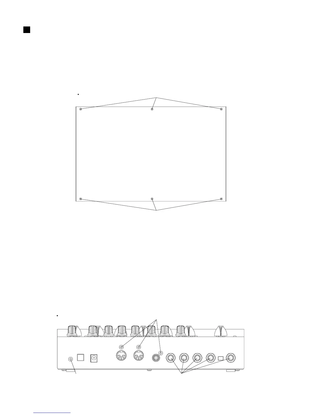
Fig.1
[30]: Bind Head Tapping Screw-B 3.0x8 MFZN2BL (EP600190)
1. Bottom Case
Remove the six (6) screws marked [30]. The bottom
case can then be removed. (Fig. 1)
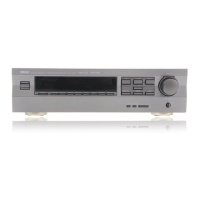
2. DM Circuit Board
2-1. Remove the bottom case. (See Procedure 1.)
2-2. Remove the four (4) screws marked [10c-a] and the
five (5) special hexagonal nuts marked [10e] from
the rear panel and the three (3) screws marked [10c-b]
from the DM circuit board. The DM circuit board can
then be removed. (Fig. 2)
Bottom
[30]
[30]
[10c-a]
Hexagonal Nut
[10c-a]
Rear