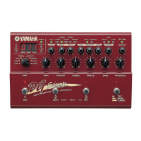
DG-Stomp
28
TEST PROGRAM
A. Connect each terminal as follows
• INPUT Monaural input
• OUT L/MONO Monaural output (RL47Kohm)
• OUT R Monaural output (RL47Kohm)
• HEAD PHONES Stereo output (323ohm each)
• EXP. PEDAL Connect VR of B50K.
Pin 1 of JK: MIN of VR, Pin 2 of JK: MAX of VR, Pin3
of JK: CENTER of VR
• DIGITAL OUT Connect the DA converter.
• MIDI IN, MIDI OUT Connect IN and OUT by using
DIN 5P cable.
• HIGH/LOW SW Used to select the input level.
OFF: 0dB, ON: +10dB
• AC IN Connect the AC adapter.
• STAND-BY SW Power switch
B. TEST PROGRAM
0: LED Check
1: SW Check
2: VR Check
3: Battery Check
4: MIDI Check
5: SRAM Check
6: DSP Check
C. STARTING THE TEST PROGRAM
While pressing the MANUAL, STORE and HALL switches,
turn on the POWER switch. The TEST program will then
be started.
D. SELECTING THE TEST NUMBER
Using the UP and DOWN switches, select the test number
and press the STORE switch to confirm selection.
E. TEST PROCEDURE
0: LED Check
• Using the UP and DOWN switches, select “0” and
then press the STORE switch.
• LED segments light up one after another starting with
“UP”. When “SP.SIM” is reached, “BANK”, “3”, “2” and
“1” light up followed by 7 segments in the following
order from the left end. After that, all LED segments
light up and go out.
1
123
7
8
4
2
3
6
5