29
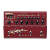
DG-Stomp
1: SW Check
• Using the UP and DOWN switches, select “1” and
then press the STORE switch.
• Starting with the UP switch, press the switches whose
LED lights up one after another. After “SP.SIM”, “BANK”,
“3”, “2” and “1”, all LED segments should light up and
then go out.
• Numbers (0 to 20) are indicated at the right end of the
7 segment LED.
• If “E” representing an error appears at the left end,
press the UTILITY switch for resetting.
2: VR Check
• Using the UP and DOWN switches, select “2” and
then press the STORE switch.
• Execute checking with “AMP SELECT” and “GAIN” to
“PRESENCE” in that order, next from “COMP” to
“REVERB” and finally until “EXP. PEDAL”
• Turn the control fully in the direction toward the left 7
segment LED which is turned on. If the test result is
OK, the right 7 segment LED lights up. Then turn the
control to that direction. If the test result is OK, proceed
to the next VR. After completing this check, return the
control to the center position.
• If an error exists outside of the control being checked,
“E” meaning an error appears at the left end. In such
case, press the UTILITY switch for resetting.
• At the end of all VR checks, all LED segments light up
and go out.
3: Battery Check
• Using the UP and DOWN switches, select “3” and
then press the STORE switch.
• If the check result is OK, all LED segments light up
and go out.
• “E” appears in case of an error.
4: MIDI Check
• Using the UP and DOWN switches, select “4” and
then press the STORE switch.
• If the check result is OK, all LED segments light up
and go out. Then checking advances to the next step.
• In case of an error, “E” is indicated by LED.
• The numeric figure at the right end of LEF represents,
0: transmission and 1: reception.
5: SRAM Check
• Using the UP and DOWN switches, select “5” and
then press the STORE switch.
• If the check result is OK, all LED segments light up
and go out.
• “0” and “1” at the right end represent IC2 and IC3
respectively.