A
1
2
3
4
5
6
7
8
DSP-A5
B
C D
E F
G H I J K
MAIN L
3
4
–27 .7
–27 .7
–27 .7
–27 .7
–27 .7
–27 .7
–25 .3
–27 .7
–27 .7
–23 .2
–23 .3
–21 .4
–25 .5
–25 .2
–27 .7
–23 .6
–13 .6
–11 .0
–13 .5
–21 .3
–19 .5
–13 .4
–25.7
–25.7
–25.7
–25.7
–25.7
–25.7
–25.7
–25.7
–25.7
–25.7
–25.7
–25.7
–25.7
–25.7
–27.7
–23.2
–23.3
–21.4
–25.5
–25.2
–27.7
–23.6
–13.6
–11.0
–13.5
–21.3
–19.5
–13.4
–25.7
0
–25.6
0
–25.7
– 27 .7
– 25 .3
– 27.7
–27.7
–27.7
–27.7
–27.7
–27.7
–27.8
0
0.5
0.4
0
4.8
4.9
0
4.8
4.9
4.8
–25.7
–25.7
–25.7
–25.7
–25.7
–25.7
–25.7
4.8
4.8
4.8
4.8
4.9
4.9
4.9
4.9
0
4.8
4.8
0
4.8
4.8
4.8
0
0.1
0
–25.7
–25.7
–25.7
–25.7
–25.7
–25.7
0
4.8
4.8
0
4.9
0
4.7
0
0
0
0
4. 8
2. 4
0
2.1
4.8
0
0
4.9
4.9
0
0
4.8
4.8
0.2
0
4.8
0
0
0
–20.4
–20.4
–25 .7
–25 .7
–27 .8
–27 .8
–20.4
–25.7
–25.6
4.9
4.9
–25.7
–11.4
4.9
4.9
4.9
0
0
2.4
2.1
–11.4
4.4
4.8
–25.7
–20.4
0.4
0
0
0
1.5
0
1.5
0
7.2
11.4
0.6
0
0
0
–27.8
–20.8
0
0
0
5.6
4.8
4.8
5.6
12.1
12.1
12.1
6.6
0.6
0.2
0.4
0
4.9
4.9
11.6
0.1
0.1
0
11.6
0
0
0
–11.2
0
0
0
–11.2
0.1
0.1
0
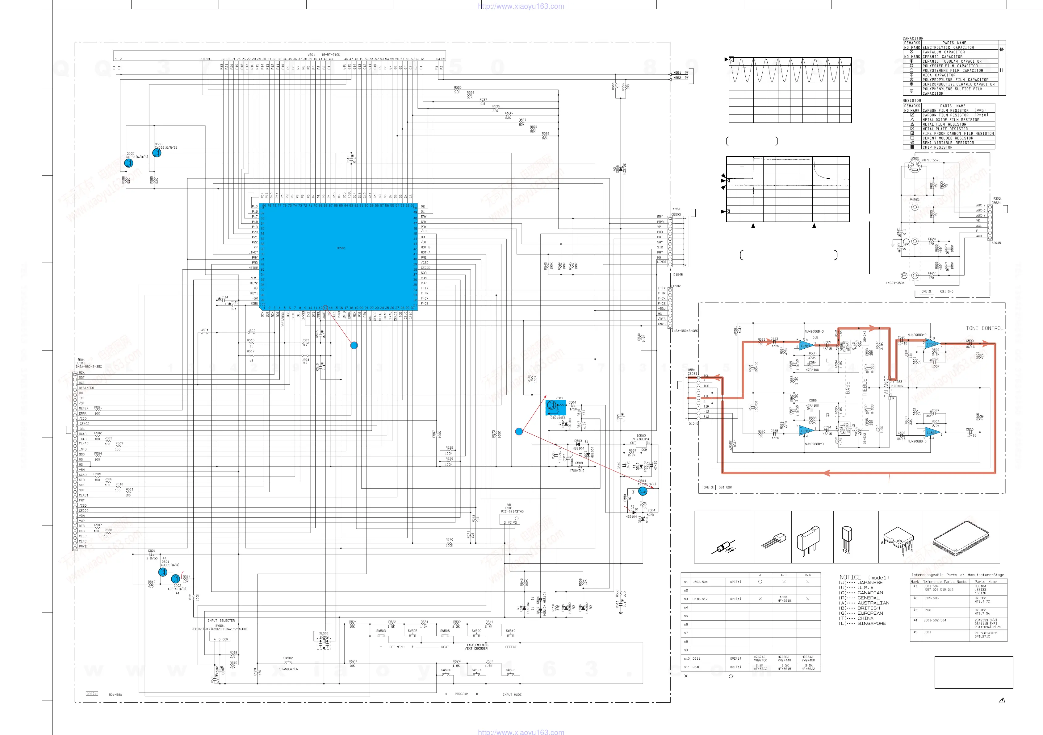
MICROCOMPUTER
TONE CONTROL
+5V
REGULATOR
POWER
DOWN
DETECT
RESET
FULL MUTE
DRIVE
TO INPUT(1) #581
page E-48/J-46
FLASH µ-COM
WRITE CONNECTOR
J-1
TO MAIN(1) #503 page E-52/J-50
I-4
FROM
POWER
TRANSFORMER
S VIDEO
AUDIO
VIDEO
VIDEO AUX
TO INPUT(2) #303
page E-49/J-47
I-5
TO INPUT(1) #501 page E-48/J-46
E-8
M30217MA-A203FP
: NOT USED : USED
E-50/J-48
■ SCHEMATIC DIAGRAM [OPERATION]
★
All voltages are measured with a 10M
Ω
/V DC electric volt meter.
★
Components having special characteristics are marked and
must be replaced with parts having specifications equal to those
originally installed.
★
Schematic diagram is subject to change without notice.
2V
SAMPLE 20us
0V
Point
3
(Pin 13 of IC501)
V : 2V/div H : 20µsec/div
DC range 1 : 1 probe
5V 2V
SAMPLE 5s
0V
(CH1)
0V
(CH2)
CH2
CH1
Disconnect the
power cord from
the AC outlet.
With the POWER
switch turned ON,
connect the
power cord to the
AC outlet.
This waveform is not available by pushing the
power switch ON and OFF.
Point
4
CH1 : Emitter of Q504
CH2 : Collector of Q503
V : 5V or 2V/div H : 5sec/div
DC range 1 : 1 probe
Conditions (DSP-A5)
• INPUT → CD
• VOLUME → minimum(–∞)
• IMPEDANCE
SELECTOR → Left
• PRO LOGIC → On
•
IC501:M30217MA-A203FP
→See page 20~22(EX),
18~20(J)
PIN CONNECTION DIAGRAM OF DIODES, TRANSISTORS AND IC’s.
2SC4038(Q,R,S)1SS133
1SS176
HSS104
HZS5B2TD
HZS6B2TD
NJM78L05A-T3
Anode
Cathode
2SA933S(Q,R)
DTC144ES
E
C
B
E
C
B
HZS7A2TD
HZS7B2TD
1:INPUT
2:COMMON
3:OUTPUT
NJM2068D-D M30217MA-A203FP
1
30
31
5051
80
81
100
w
w
w
.
x
i
a
o
y
u
1
6
3
.
c
o
m
Q
Q
3
7
6
3
1
5
1
5
0
9
9
2
8
9
4
2
9
8
T
E
L
1
3
9
4
2
2
9
6
5
1
3
9
9
2
8
9
4
2
9
8
0
5
1
5
1
3
6
7
3
Q
Q
TEL 13942296513 QQ 376315150 892498299
TEL 13942296513 QQ 376315150 892498299
http://www.xiaoyu163.com
http://www.xiaoyu163.com
 Loading...