EasyManua.ls Logo

Yamaha DSP-A595 Service Manual

Yamaha DSP-A595
61 pages
To Next Page IconTo Next Page
Page #1 background imageLoading...
Page #1 background image
SERVICE MANUAL
IMPORTANT NOTICE
This manual has been provided for the use of authorized YAMAHA Retailers and their service personnel.
It has been assumed that basic service procedures inherent to the industry, and more specifically YAMAHA
Products, are already known and understood by the users, and have therefore not been restated.
WARNING: Failure to follow appropriate service and safety procedures when servicing this product
may result in personal injury, destruction of expensive components, and failure of the
product to perform as specified. For these reasons, we advise all YAMAHA product
owners that any service required should be performed by an authorized YAMAHA
Retailer or the appointed service representative.
IMPORTANT:The presentation or sale of this manual to any individual of firm does not constitute
authorization, certification or recognition of any applicable technical capabilities,
or establish a principle-agent relationship of any form.
The data provided is believed to be accurate and applicable to the unit(s) indicated on the cover. The research,
engineering, and service departments of YAMAHA are continually striving to improve YAMAHA products.
Modifications are, therefore, inevitable and specifications are subject to change without notice or obligation
to retrofit. Should any discrepancy appear to exist, please contact the distributor's Service Division.
WARNING: Static discharges can destroy expensive components. Discharge any static electricity
your body may have accumulated by grounding yourself to the ground buss in the unit
(heavy gauge black wires connect to this buss).
IMPORTANT:Turn the unit OFF during disassembly and part replacement. Recheck all work before
you apply power to the unit.
100661
AV AMPLIFIER
DSP-A595
TO SERVICE PERSONNEL ........................................... 1
REMOTE CONTROL PANELS ....................................... 1
REAR PANELS ............................................................... 2
SPECIFICATIONS....................................................... 3~4
INTERNAL VIEW ............................................................ 5
DISASSEMBLY PROCEDURES .................................... 5
SELF DIAGNOSIS FUNCTION ................................ 6~17
FACTORY PRESET ...................................................... 18
CONTENTS
AMP ADJUSTMENT ..................................................... 19
IC DATA .................................................................. 20~29
DISPLAY DATA ........................................................... 30
BLOCK DIAGRAM .................................................. 31~32
PRINTED CIRCUIT BOARD ................................... 33~46
SCHEMATIC DIAGRAM ......................................... 47~52
PARTS LIST ............................................................ 53~66
REMOTE CONTROL TRANSMITTER ......................... 67
w
w
w
.
x
i
a
o
y
u
1
6
3
.
c
o
m
Q
Q
3
7
6
3
1
5
1
5
0
9
9
2
8
9
4
2
9
8
T
E
L
1
3
9
4
2
2
9
6
5
1
3
9
9
2
8
9
4
2
9
8
0
5
1
5
1
3
6
7
3
Q
Q
TEL 13942296513 QQ 376315150 892498299
http://www.xiaoyu163.com

Other manuals for Yamaha DSP-A595

Question and Answer IconNeed help?

Do you have a question about the Yamaha DSP-A595 and is the answer not in the manual?

Yamaha DSP-A595 Specifications

General IconGeneral
Channels5
Frequency Response20 Hz - 20 kHz
Channel separation60 dB
Speaker load impedance4-16 Ohms
Dimensions17 x 5.5 x 15.5 inches
Weight24.2 lbs
TypeAV Receiver
Input Sensitivity200mV (line)
Signal to Noise Ratio100 dB
Video ConnectionsComposite Video, S-Video
Power Output per channel70 Watts (8 Ohms, 20 Hz - 20 kHz, 0.04% THD)

Summary

TO SERVICE PERSONNEL

REMOTE CONTROL PANELS

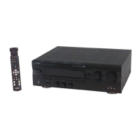
Describes the layout and functions of the remote control for different models.

REAR PANELS

Illustrates the rear panel connections and labels for various models.

SPECIFICATIONS

Details technical specifications for audio, video, and general aspects of the unit.

DIMENSIONS

Provides physical dimensions of the unit in millimeters and inches.

REMOTE CONTROL SCHEMATIC

Shows the schematic diagram for the remote control transmitter's circuitry.

SELF DIAGNOSIS FUNCTION

BEGINNING AND CANCELLATION

Explains how to start and exit the self-diagnosis program and display.

RELEASING METHOD

Details the procedures to exit the self-diagnosis function and reset backup memory.

OPERATION AND DISPLAY WHEN STARTING DIAGNOSIS FUNCTION

Describes menu selection methods and other functions active during diagnosis.

ANALOG THROUGH

Explains the analog signal path and bypass circuits for diagnostic testing.

DSP THROUGH

Details diagnostic modes for DSP processing of digital and analog signals.

AC3 THROUGH

Describes AC3 digital signal input and decoding operation for diagnostics.

PRO LOGIC

Explains PRO LOGIC decoding and signal switching for diagnostic modes.

SPEAKERS SET

Covers speaker settings and their corresponding signal path configurations for diagnosis.

DISPLAY CHECK

Describes the FL display check program for detecting driver and segment defects.

MANUAL TEST

Details the manual test function using the DSP's built-in noise generator.

FACTORY PRESET

Explains how to set backup data to factory preset state and reset protection data.

AD DATA CHECK

Describes the A/D conversion values for detecting key scan and protection status.

STATUS FROM DSP MICOM

Displays status data from the DSP microprocessor in hexadecimal format.

CPU VERSION/CHECK SUM/PORT INFO/EXIT DIAG

Shows CPU version, check sum, and port settings for main and DSP microprocessors.

FACTORY PRESET

AMP ADJUSTMENT

Confirmation of Idling Current of Main Amplifier

Explains how to measure and adjust the idling current of the main amplifier for optimal performance.

IC DATA

INTERNAL VIEW

DISASSEMBLY PROCEDURES

Provides step-by-step instructions for disassembling the unit, starting with the top cover.

BLOCK DIAGRAM

DISPLAY DATA

PRINTED CIRCUIT BOARD (Foil side)

SCHEMATIC DIAGRAM (INPUT)

SCHEMATIC DIAGRAM (MAIN)

SCHEMATIC DIAGRAM (OPERATION)

PARTS LIST

EXPLODED VIEW

MECHANICAL PARTS

Related product manuals