RX-V530/RX-V530RDS/HTR-5550/HTR-5550RDS/DSP-AX530
RX-V430/RX-V430RDS/HTR-5540/HTR-5540RDS/DSP-AX430
RX-V530/RX-V530RDS/HTR-5550/HTR-5550RDS/DSP-AX530
RX-V430/RX-V430RDS/HTR-5540/HTR-5540RDS/DSP-AX430
18
6
7
6
6
8
CB308
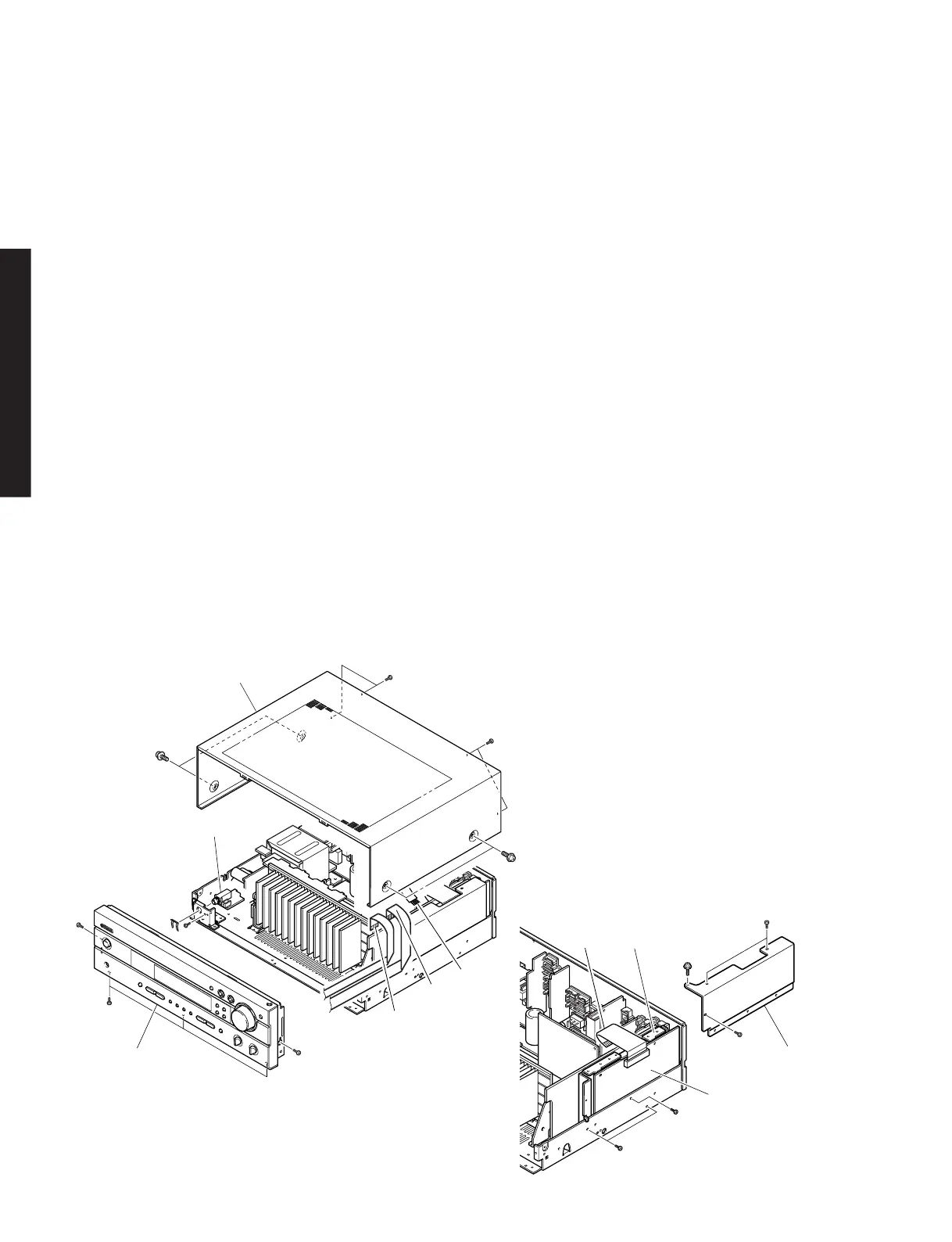
■ DISASSEMBLY PROCEDURE/分解手順
Fig. 1
(Remove parts in the order as numbered.)
Disconnect the power cord from the AC outlet.
1. Removal of Top Cover
a. Remove 4 screws (1) and 4 screws (2). (Fig. 1)
b. Slide the Top Cover rearward to remove it. (Fig. 1)
2. Removal of Front Panel Unit
a. Remove 5 screws (3) and then remove the Front Panel
Unit. (Fig. 1)
b. Remove 309~311. (Fig. 1)
c. Loosen the harness fixture fixing the cable.
3. Removal of MAIN (5) P.C.B.
a. Remove 1 screw (4) and then remove the Jack
Stopper (5) upward. (Fig. 1)
b. Remove the MAIN (5) P.C.B.. (Fig. 1)
4. Removal of DSP P.C.B.
a. Remove 4 screws (6 ) and 1 screw (7), and then
remove the Shield Case Cover. (Fig. 2)
b. Remove 2 screws (8). (Fig. 2)
c. RX-V530/RX-V530RDS/HTR-5550/HTR-5550RDS/
DSP-AX530: Remove 5 screws (9). (Fig. 3)
RX-V430/RX-V430RDS/HTR-5540/HTR-5540RDS/
DSP-AX430: Remove 2 screws (9). (Fig. 3)
d. Remove CB308. (Fig. 2)
e. Remove the Shield Case and the DSP P.C.B.. (Fig. 2)
1. トップカバーの外し方
12
2. フロントパネルユニットの外し方
3
3. MAIN(5)P.C.B.の外し方
45
4. DSPP.C.B.の外し方
67
8
9
9
Fig. 2
2
2
1
1
4
5
3
3
3
MAIN (5) P.C.B.
CB311
CB310
CB309