RX-V530/RX-V530RDS/HTR-5550/HTR-5550RDS/DSP-AX530
RX-V430/RX-V430RDS/HTR-5540/HTR-5540RDS/DSP-AX430
RX-V530/RX-V530RDS/HTR-5550/HTR-5550RDS/DSP-AX530
RX-V430/RX-V430RDS/HTR-5540/HTR-5540RDS/DSP-AX430
20
6. MAIN(1)、MAIN(3)、MAIN(4)、FUNCTION
(5)P.C.B.の外し方
BC
7. RX-V530/RX-V530RDS/HTR-5550/HTR-
5550RDS/DSP-AX530/RX-V430RDS/HTR-
5540RDS:MAIN(7)、MAIN(2)P.C.B.の外し方
D
E
F
6. Removal of MAIN (1), MAIN (3), MAIN (4) and
FUNCTION (5) P.C.B.s
a. Remove CB253. (Fig. 6)
b. Remove 1 screw (B) and 2 screws (C). (Fig. 6)
c. Remove FUNCTION (1) ~ (4), FUNCTION (10), VIDEO
(1) and VIDEO (2) P.C.B.s. and the Tuner. (Fig. 6)
7. RX-V530/RX-V530RDS/HTR-5550/HTR-5550RDS/
DSP-AX530/RX-V430RDS/HTR-5540RDS: Removal
of MAIN (7) and MAIN (2) P.C.B.s
a. Remove 1 screw (D). (Fig. 3)
b. Remove MAIN (7) P.C.B.. (Fig. 6)
c. Remove 1 screw (E). (Fig. 3)
d. Remove 1 screw (F). (Fig. 6)
e. Remove MAIN (2) P.C.B.. (Fig. 6)
Fig. 4
Fig. 5
Tuner
VIDEO (2) P.C.B. *1
VIDEO (1) P.C.B. *1
FUNCTION (2) P.C.B.
FUNCTION (3) P.C.B.
FUNCTION (1) P.C.B.
FUNCTION (4) P.C.B.
FUNCTION (10) P.C.B.
*1: RX-V530/RX-V530RDS/HTR-5550/HTR-5550RDS/DSP-AX530 only
A
CB312
5. RX-V430/RX-V430RDS/HTR-5540/HTR-
5540RDS/DSP-AX430:FUNCTION(1)〜(4)、
FUNCTION(10)P.C.B.、TUNERの外し方
0
A
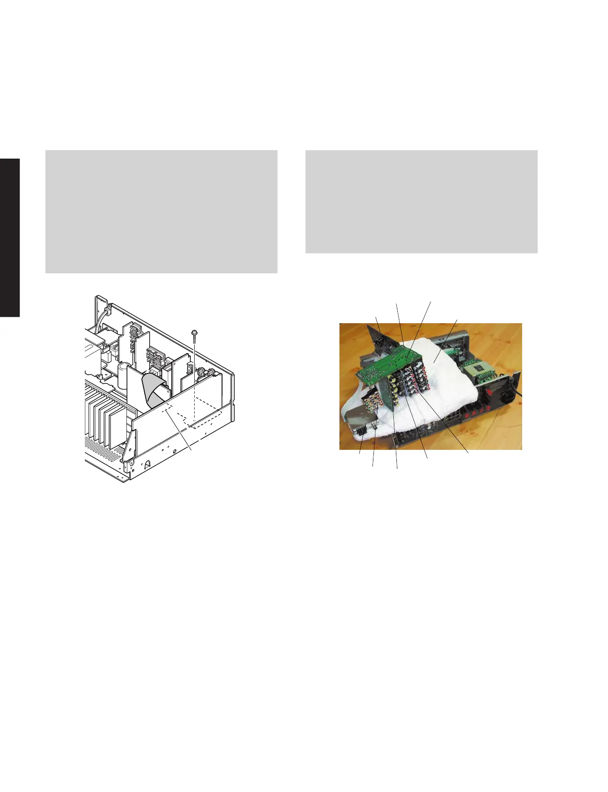
P.C.B.チェックをする場合には
When checking the P.C.B.:
•
Put the rubber sheet and a cloth over the equipment.
Then place the P.C.B. upside down on the cloth and
check it. (Fig. 5)
• Reconnect all cables (connectors) that have been
disconnected.
• The P.C.B. removed from the rear panel does not
work because its grounding is loose. Be sure to
connect the ground of each P.C.B. to the chassis or
GND with a jumper wire or the like.
5. RX-V430/RX-V430RDS/HTR-5540/HTR-5540RDS/
DSP-AX430: Removal of FUNCTION (1) ~ (4),
FUNCTION (10) P.C.B.s and Tuner
a. Remove CB312. (Fig. 4)
b. Remove 15 screws (0). (Fig. 3)
c. Remove 1 screw (A). (Fig. 4)
d. Remove FUNCTION (1) ~ (4), FUNCTION (10)
P.C.B.s. and the Tuner. (Fig. 4)