RX-V463/HTR-6450/DSP-AX463
16
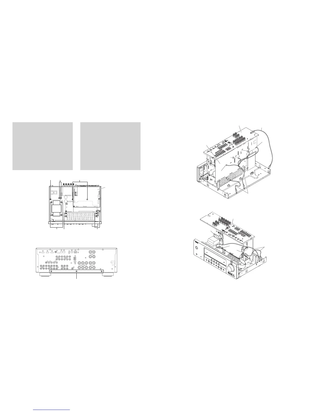
Fig. 6
Fig. 5
When checking the P.C.B.:
a. Remove the top cover. (Fig. 1)
b. Remove DSP P.C.B.. (Fig. 2)
c. Remove 6 screws (0). (Fig. 5)
d. Remove 2 screws (A). (Fig. 5)
e. Remove 3 screws (B). (Fig. 6)
f. Remove 2 screws (C). (Fig. 5)
g. Remove 4 screws (D). (Fig. 5)
h. Place the P.C.B. upright. (Fig. 7)
i. The P.C.B. removed from the chassis does not work
because its grounding is loose.
Be sure to connect the ground of rear panel and MAIN
(1) P.C.B. (G5004, G5005, G5006 and G3401) and
DSP P.C.B. (G801 and G802) to the chassis with a
ground lead or the like. (Fig. 7)
Fig. 7
0
0
A
0
C
D
DSP P.C.B.
B
M
A
IN
(1
) P
.C
.B
.
Ground lead
Ground lead
Rear panel
G5005
G5004
G5006
G3401
Rear panel
DSP P.C.B.
G802
G801
Ground lead
P.C.B.チェックをする場合には:
a. トップカバーを取り外します。(Fig.1)
b. DSPP.C.B.を取り外します。(Fig.2)
c.
0
のネジ6本を外します。(Fig.5)
d.
A
のネジ2本を外します。(Fig.5)
e.
B
のネジ3本を外します。(Fig.6)
f.
C
のネジ2本を外します。(Fig.5)
g. Dのネジ4本を外します。(Fig.5)
h. P.C.B.を立ち上げて置きます。(Fig.7)
i. シャーシから外したP.C.B.はアースが浮いて動作しま
せんので、リアパネルおよびMAIN(1)P.C.B.の
G5004、G5005、G5006、G3401とDSPP.C.B.の
G801、G802のアースをリード線等でシャーシに接続
してください。(Fig.7)
 Loading...


