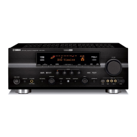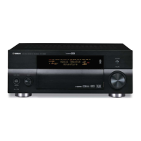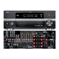
Do you have a question about the Yamaha DSP-AX463 and is the answer not in the manual?
Procedure for verifying insulation and measuring leakage current on 120V models.
Detailed specifications for the audio section, including output power, frequency response, and distortion.
Detailed specifications for the video section, including signal types and levels.
Step-by-step instructions for removing the top cover of the unit.
Step-by-step instructions for removing the front panel unit.
Instructions for removing the VIDEO (1) and (2) P.C.B.s.
Instructions for removing the VIDEO (4) P.C.B.
Instructions for removing the FM/AM tuner module.
Notes for U, C, T, K, G, E, F models regarding self-diagnostic and Model ID settings.
List of necessary tools and the firmware CD for updating.
Step-by-step guide for connecting equipment and updating firmware.
Steps to connect and operate a DVD/CD player for firmware writing.
Procedure to initialize the unit after a firmware update.
Using self-diagnostic menu S1 to confirm the firmware version.
Using self-diagnostic menu S2 to confirm the checksum value.
Using self-diagnostic menu S3 to confirm the program checksum.
Purpose of self-diagnostic functions for inspection and fault finding.
List of main and sub-menu items available in the self-diagnostic function.
Procedure to start diagnostics with protection functions disabled.
Procedure to cancel the self-diagnostic function and restore settings.
Display indication when no protection history is recorded.
Display indication when protection history is recorded.
Explanation of protection activation due to excessive current in the power amplifier.
Important notes regarding applying power with protection functions disabled or abnormal conditions.
Explanation of protection activation due to abnormal voltage in the power supply section.
Information on how protection history is stored in memory and how it can be cleared.
Information on what the FL display indicates during menu operations.
Instructions on how to select main menu items using program keys.
Instructions on how to select sub-menu items using scene keys.
Explains the selection between analog bypass and DSP bypass outputs.
Details on outputting analog input signals to FRONT L/R with EFFECT OFF.
Details on outputting digital input signals to FRONT L/R with EFFECT OFF.
Details on outputting input sound signals and their distribution.
Explanation of LIM, PLDET, and THM parameters for diagnostic checks.
Displays A/D setting values for each protection function.
Verification of microprocessor, checksum, SPI, and SPD firmware details.
Block diagram illustrating the audio digital signal path and components.
Block diagram showing the DSP control signal flow and interfaces.
Block diagram illustrating audio analog signal path and power supply connections.
Block diagram showing the video signal path and processing.
Block diagram illustrating control signals and interfaces to various sections.
Schematic diagram detailing the DSP section, part 1 of 8.
List of electrical components for replacement, with warnings and notes.
Information regarding new parts added for the DSP PCB.
Further new parts information for the DSP PCB.
Information regarding new parts for MAIN and VIDEO PCBs.
Information regarding new parts for the OPERATION PCB.
Information regarding new parts for the MAIN PCB.
Additional new parts information for the MAIN PCB.
Information regarding new parts for the VIDEO PCB.
Further new parts information for the VIDEO PCB.


 Loading...