RX-V740/RX-V740RDS/DSP-AX740
RX-V640/RX-V640RDS/HTR-5660/DSP-AX640/DSP-AX640SE
19
RX-V740/RX-V740RDS/DSP-AX740
RX-V640/RX-V640RDS/HTR-5660/DSP-AX640/DSP-AX640SE
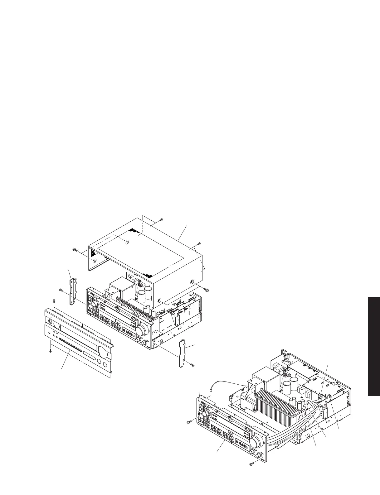
CB306
CB572
CB305
CB604
CB605
5
5
Sub Chassis
■ DISASSEMBLY PROCEDURES/分解手順
* The description below uses RX-V740RDS (G model) as
a representative model.
(Remove parts in the order as numbered.)
Disconnect the power cable from the AC outlet.
1. Removal of Top Cover
a. Remove 4 screws (1) and 4 screws (2). (Fig. 1)
b. Slide the Top Cover rearward to remove it. (Fig. 1)
2. Removal of Front Panel
Remove 6 screws (3) and then remove the Front Panel.
(Fig. 1)
3. Removal of Sub Chassis
a. Remove 2 push rivets (4) and then remove the Side
Plates. (Fig. 1)
b. Remove 2 screws (5) and then remove the Sub
Chassis. (Fig. 2)
c. Loosen the harness fixture fixing the cable.
d. Remove CB305, 306, 572, 604 and 605. (Fig. 2)
1. トップカバーの外し方
12
2. フロントパネルの外し方
3
3. サブシャーシの外し方
4
5
Fig. 2
Top Cover
Front Panel Unit
Side Plate
Side Plate
1
1
3
3
4
4
2
2
Fig. 1
 Loading...


