RX-V740/RX-V740RDS/DSP-AX740
RX-V640/RX-V640RDS/HTR-5660/DSP-AX640/DSP-AX640SE
21
RX-V740/RX-V740RDS/DSP-AX740
RX-V640/RX-V640RDS/HTR-5660/DSP-AX640/DSP-AX640SE
5. FUNCTION(1)〜(6)、TUNERの外し方
8
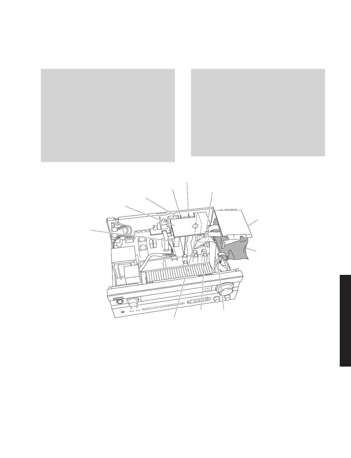
5. Removal of FUNCTION (1) ~ (7) P.C.B.s and Tuner
a. Remove CB104, CB304 and CB307. (Fig. 3)
b. Remove 23 screws (8). (Fig. 3)
c. Remove FUNCTION (1) ~ (7) P.C.B.s. and the Tuner.
(Fig. 5)
P.C.B.チェックをする場合には
POWER (1) P.C.B. CB601 – FUNCTION (1) P.C.B. CB307:
MF117200 (17P 200mm)
When checking the P.C.B.:
• Reconnect all cables (connectors) that have been
disconnected.
Be sure to use the extension cable for servicing for
the following section.
POWER (1) P.C.B. CB601 – FUNCTION (1) P.C.B. CB307:
MF117200 (17P 200mm)
• When connecting the flat cable, use care for the
polarity.
• The P.C.B. removed from the rear panel does not
work because its grounding is loose. Be sure to
connect the ground of each P.C.B. to the chassis or
GND with a jumper wire or the like.
FUNCTION (3) P.C.B.
P.C.B.
FUNCTION (7) P.C.B. (except J model)
FUNCTION (5) P.C.B.
FUNCTION (4) P.C.B.
FUNCTION (6) P.C.B.
FUNCTION (1) P.C.B.
FUNCTION (2) P.C.B.
Tuner
MF117200
Fig. 5
 Loading...


