RX-V740/RX-V740RDS/DSP-AX740
RX-V640/RX-V640RDS/HTR-5660/DSP-AX640/DSP-AX640SE
A
1
2
3
4
5
6
7
8
9
BCDEFGH I JKL
92
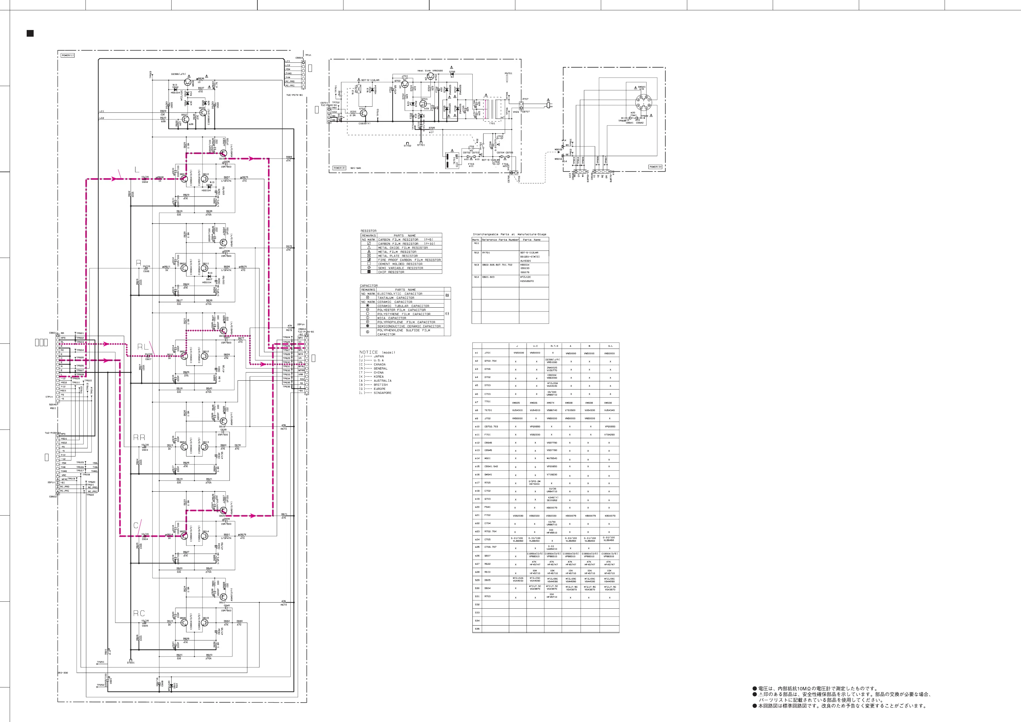
SCHEMATIC DIAGRAM (POWER)
★ All voltages are measured with a 10MΩ/V DC electric volt meter.
★ Components having special characteristics are marked s and must be replaced
with parts having specifications equal to those originally installed.
★ Schematic diagram is subject to change without notice.
x: NOT USED
O: USED / APPLICABLE
to MAIN (3)
Page 91 H2
to MAIN (1)
Page 91 A4
to MAIN (1)
Page 91 A1
to MAIN (2)
Page 91 F6
to Power Transformer
(U, C, A, B, G, L, J models)
to Power Transformer
(R, T, K models)
VOLTAGE
SELECTOR
POWER RELAY
RX-640/RX-V640RDS/HTR-5660/DSP-AX640: Page 84 J4
DSP-AX640SE: Page 86 J4
RX-740/RX-V740RDS/DSP-AX740: Page 82 J4
to FUNCTION (1)
MAIN L
REAR L
CENTER
55.1
55.2
43.1 43.1
28.3
1.1
0
0
54.7
54.7
0
0.1
0.1
0
35.9
54.7
54.2
53.6
0
53.6
-0.6
-0.6
1.2
0
0
54.6
54.2
53.6
0
53.6
-0.6
-0.6
1.1
0
54.7
54.2
53.6
0
53.6
-0.6 -0.6
1.2
0
54.7
46.4
45.8
0
53.6
-0.6 -0.6
1.1
0
54.7
54.2
53.6
0
53.6
-0.6 -0.6
1.1
0
54.7
-12.1
0
54.2
53.6
0
53.6
-0.6 -0.6
13.6
0.1
0
6.3
0
6.3
0
13.6
13.6
0.1
0.8
AC
13.3
 Loading...


