RX-V740/RX-V740RDS/DSP-AX740
RX-V640/RX-V640RDS/HTR-5660/DSP-AX640/DSP-AX640SE
45
RX-V740/RX-V740RDS/DSP-AX740
RX-V640/RX-V640RDS/HTR-5660/DSP-AX640/DSP-AX640SE
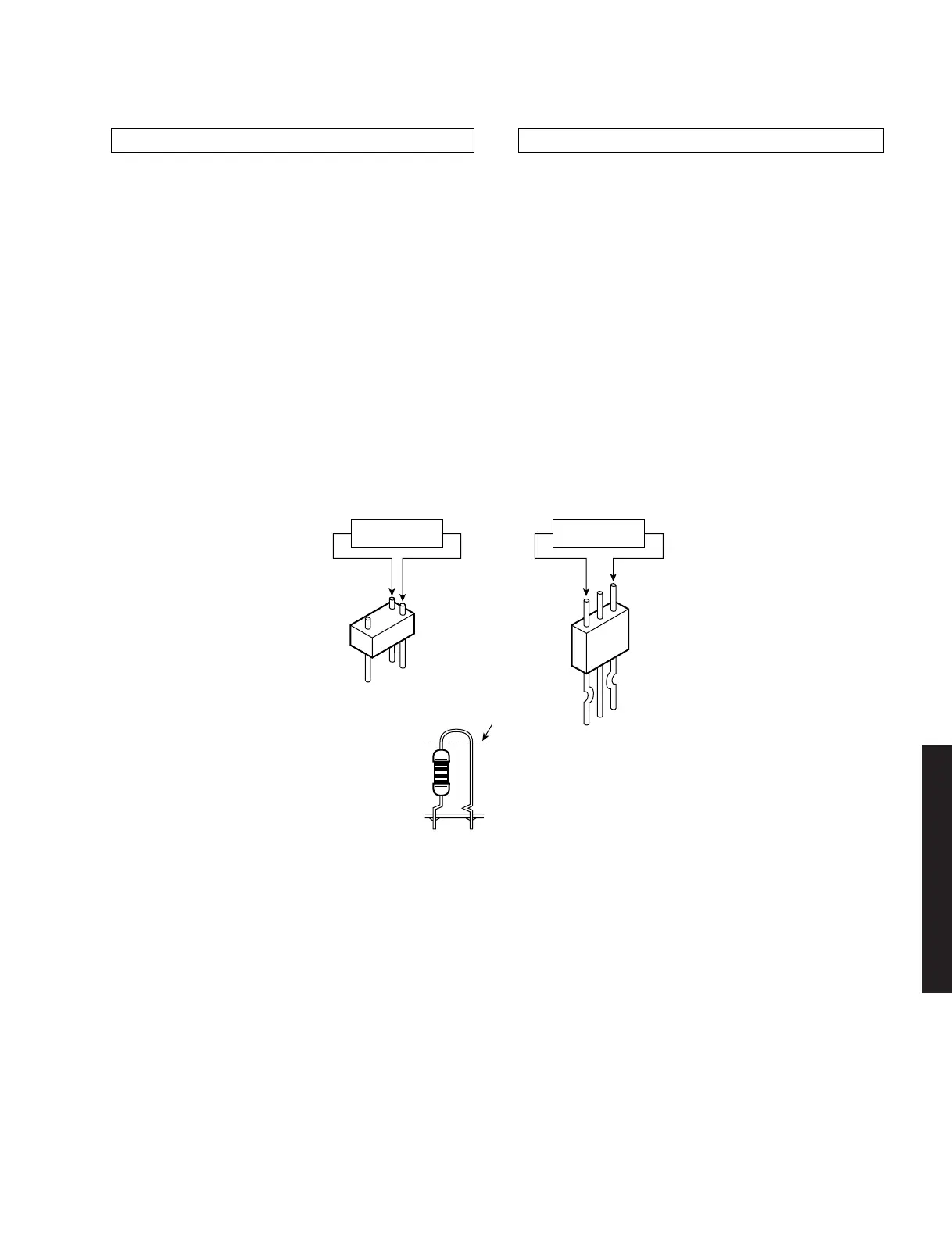
■ AMP ADJUSTMENT/アンプ部調整
0.1mV ~ 10.0mV
(DC)
0.1mV ~ 10.0mV
(DC)
R164 (MAIN Lch)
R168 (MAIN Rch)
R181 (CENTER)
R109 (MAIN Lch)
R116 (MAIN Rch)
R136 (CENTER)
R122 (REAR Lch)
R129 (REAR Rch)
R403 (REAR Cch)
R175 (REAR Lch)
R177 (REAR Rch)
R416 (REAR Cch)
Cut off
カット
Confirmation of Idling Current of Main (1) P. C. B.
• Right after power is turned on, confirm that the voltage
across the terminals of R164 (Main Lch), R168 (Main
Rch), R181 (Center), R175 (Rear Lch), R177 (Rear
Rch), R416 (Rear Cch) are between 0.1mV and
10.0mV.
• If it exceeds 10.0mV, open (cutoff) R109 (Main Lch),
R116 (Main Rch), R136 (Center), R122 (Rear Lch),
R129 (Rear Rch), R403 (Rear Cch) and reconfirm the
voltage.
Attention
If the idle current exceeds 10.0mV after an amplifier
repair, first check for a defective component before
cutting the bias resistor.
• Confirm that the voltage is 0.2mV ~ 15.0mV after 60
minutes.
メイン(1)基板のアイドリング電流の確認
注意
 Loading...


