RX-V740/RX-V740RDS/DSP-AX740
RX-V640/RX-V640RDS/HTR-5660/DSP-AX640/DSP-AX640SE
RX-V740/RX-V740RDS/DSP-AX740
RX-V640/RX-V640RDS/HTR-5660/DSP-AX640/DSP-AX640SE
46
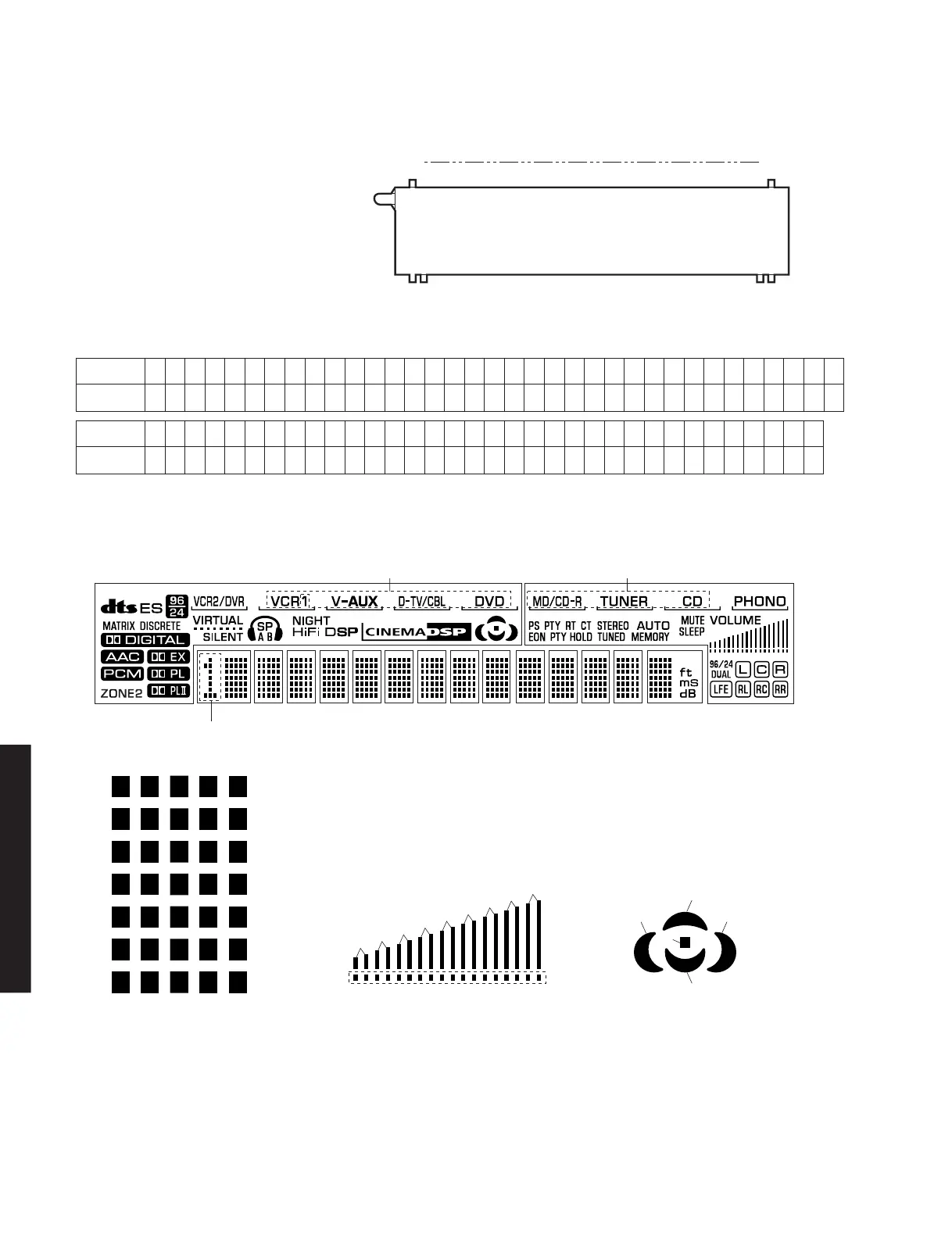
■ DISPLAY DATA
● V501 : 16-BT-108GNK (WA292900)
● PIN CONNECTION
● GRID ASSIGNMENT
Pin No.
Connection
Pin No.
69
F2
68
F2
67
NP
66
NP
65
P1
64
P2
63
P3
62
P4
61
P5
60
P6
59
P7
58
P8
57
P9
56
P10
55
P11
54
P12
53
P13
52
P14
51
P15
50
P16
49
P17
48
P18
47
P19
46
P20
45
P21
44
P22
43
P23
42
P24
41
P25
40
P26
39
P27
38
P28
37
P29
34
P32
33
P33
32
P34
31
P35
30
P36
29
P37
28
P38
27
NX
26
NX
25
NX
24
NX
23
NX
22
NX
21
NX
20
16G
19
15G
18
14G
17
13G
16
12G
15
11G
14
10G
13
9G
12
8G
11
7G
10
6G
9
5G
8
4G
7
3G
6
2G
5
1G
4
NP
3
NP
36
P30
35
P31
2
F1
1
F1
Connection
Note : 1) F1, F2 ..... Filament 2) NP ..... No pin 3) G1 ~ 16 ..... Grid 4) NX ..... No extened 5) P1 ~ 38 ..... Anode
(1G~14G) (15G) (16G)
1-1
1-2
1-3
1-4
1-5
1-6
1-7
2-1
2-2
2-3
2-4
2-5
2-6
2-7
3-1
3-2
3-3
3-4
3-5
3-6
3-7
4-1
4-2
4-3
4-4
4-5
4-6
4-7
5-1
5-2
5-3
5-4
5-5
5-6
5-7
PATTERN AREA
16G 2G1G 3G 4G 5G 6G 7G 11G10G9G8G 12G 13G 14G 15G
S12
B1
B2
}1
B3
B4
B5
B6
B7
B8
B9
B10
S14
S17
S13
S16S15
S1 S7
 Loading...


