RX-V740/RX-V740RDS/DSP-AX740
RX-V640/RX-V640RDS/HTR-5660/DSP-AX640/DSP-AX640SE
52
GND
RST
VCC
ZIN1
CSCSI
SDMI
TIN
SCKI
MEMACS
ZOUT
YOUT
TOUT[0]
VCC
SDDO
ABOOT
EMWRIN
GND
TDO
EMOEIN
PGND
NC
SDMO
PGND
SCKO
TIE
100
99 98 97 96 95 94 93 92 91 90 89 88 87 86 85 84 83 82 81 80 79 78 77 76
ZIN2 1 75 GND
NC 2 74 CSIO[7]
ZIN3 3 73 NC
PGND 4 72 CSIO[6]
VCC 5 71 CSIO[5]
FMEMENINV 6 70 CSIO[4]
NC 7 69 GND
FMEMEN 8 68 CSIO[3]
EXMEMON 9 67 CSIO[2]
EMWRON 10
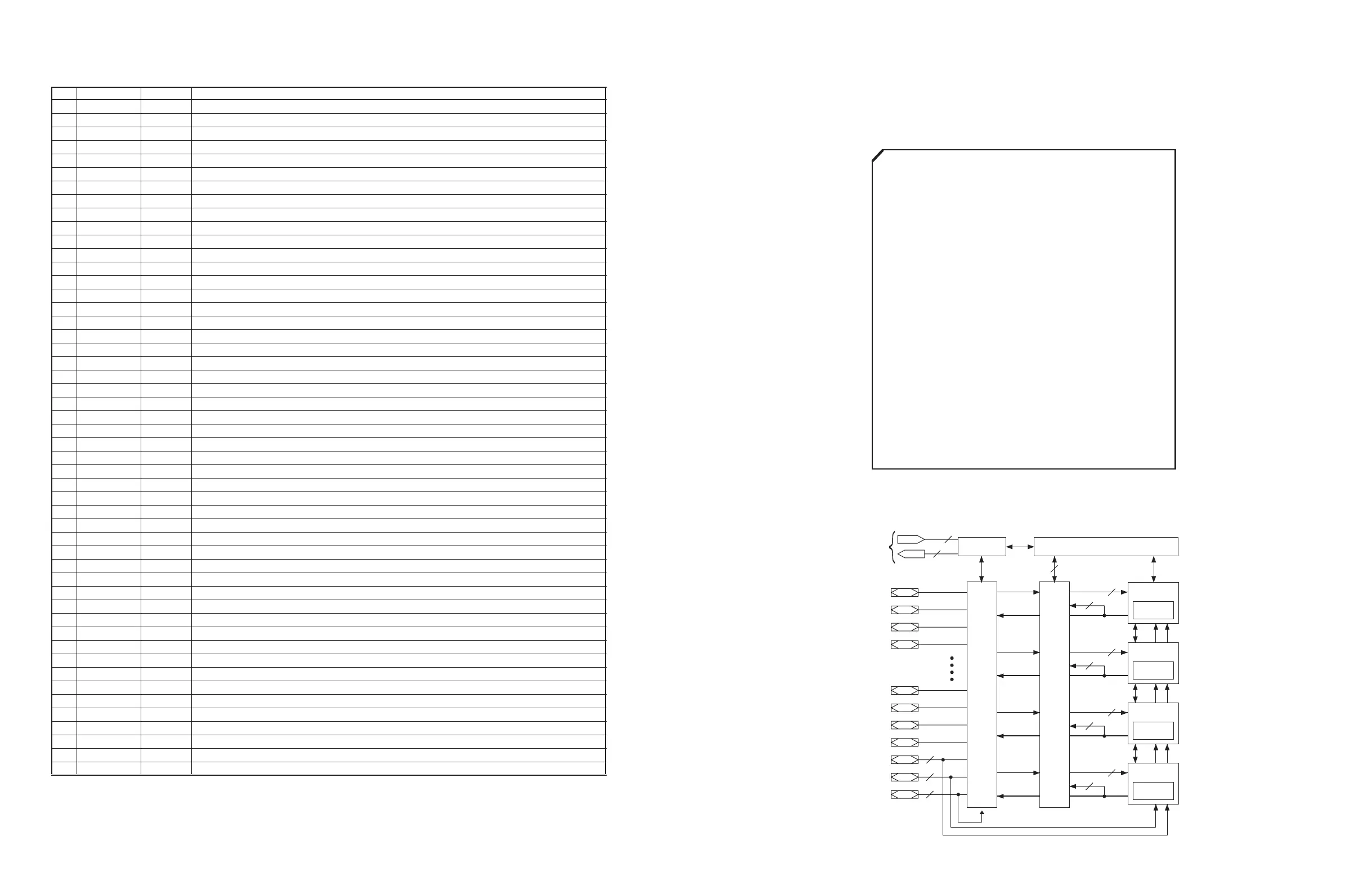
PLD
66 CSIO[1]
PAGE[0] 11
XC9572XL-10TQ100
65 CSIO[0]
PAGE[1] 12 64 ZSEL[0]
PAGE[2] 13 63 XOUT
PAGE[3] 14 62 GND
A[0] 15 61 CSCSO
A[1] 16 60 PGND
A[2] 17 59 EXMEMIN
A[3] 18 58 D[7]
NC 19 57 VCC
ZSEL[1] 20 56 D[6]
GND 21 55 D[5]
CSPLDI 22 54 D[4]
XIN1 23 53 D[3]
NC 24 52 D[2]
XIN2 25 51 VCC
26 27 28 29 30 31 32 33 34 35 36 37 38 39 40 41 42 43 44 45 46 47 48 49 50
VCC
A[4]
A[5]
A[6]
A[7]
GND
A[8]
A[9]
NC
A[10]
A[11]
A[12]
VCC
A[13]
A[14]
YIN1
YIN2
NC
GND
TDI
NC
TMS
TCK
D[0]
D[1]
I/O
Function
Block 1
Macrocells
1 to 18
I/O
Blocks
JTAG
Controller
In-System Programming Controller
Fast CONNECT II Switch Matrix
I/O
I/O
I/O
I/O
I/O
I/O
I/O
I/O/GCK
I/O/GSR
I/O/GTS
2
54
18
1
JTAG Port
1
3
3
Function
Block 1
Macrocells
1 to 18
54
18
Function
Block 1
Macrocells
1 to 18
54
18
Function
Block 1
Macrocells
1 to 18
54
18
Is: Schmidt trigger input terminal
I+: Input terminal with pull-up resistor
O: Digital output terminal
Ot: 3-state digital output terminal
A: Analog terminal
No. Name I/O Function
111 RAMA5 O Sub DSP: External memory address terminal 5
112 RAMA2 O Sub DSP: External memory address terminal 2
113 SELI13 I+ Built-in selector input 13 (Unconnected)
114 SELI12 I+ Built-in selector input 12
115 SELI11 I+ Built-in selector input 11 (Unconnected)
116 SELI10 I+ Built-in selector input 10 (Unconnected)
117 SELI9 I+ Built-in selector input 9 (CXB)
118 RAMA4 O Sub DSP: External memory address terminal 4
119 RAMA3 O Sub DSP: External memory address terminal 3
120 RAMA9 O Sub DSP: External memory address terminal 9 (Unconnected)
121 RAMA10 O Sub DSP: External memory address terminal 10 (Unconnected)
122 RAMA11 O Sub DSP: External memory address terminal 11 (Unconnected)
123 VSS Ground terminal
124 VDD2 +2.5V power terminal (for internal circuit)
125 SELI8 I+ Built-in selector input 8 (CXA)
126 SELI7 I+ Built-in selector input 7 (GND)
127 SELI6 I+ Built-in selector input 6 (OPTF)
128 SELI5 I+ Built-in selector input 5 (Unconnected)
129 RAMA12 O Sub DSP: External memory address terminal 12 (Unconnected)
130 RAMA13 O Sub DSP: External memory address terminal 13 (Unconnected)
131 RAMA14 O Sub DSP: External memory address terminal 14 (Unconnected)
132 RAMA15 O Sub DSP: External memory address terminal 15 (Unconnected)
133 RAMA16 O Sub DSP: External memory address terminal 16 (Unconnected)
134 RAMA17 O Sub DSP: External memory address terminal 17 (Unconnected)
135 OVFB/END O Sub DSP: Overflow/program end detect terminal (Unconnected)
136 ZEROFLG O Main DSP: Zero flag output terminal (Unconnected)
137 VSS Ground terminal
138 NONPCM O Main DSP: Non-PCM data detect terminal
139 DTSDATA O Main DSP: DTS data detect terminal (Unconnected)
140 AC3DATA O Main DSP: AC3 data detect terminal (Unconnected)
141 MUTE O Main DSP: Auto mute detect terminal
142 KARAOKE O Main DSP: AC3 KARAOKE data detect terminal (Unconnected)
143 VDD1 +3.3V power terminal (for terminal section)
144 SURENC O Main DSP: AC-3 2/0 mode Dolby surround encode input detect terminal (Unconnected)
145 CRC O Main DSP: AC3 CRC error detect terminal (Unconnected)
146 /LOCK O DIR: PLL lock detect terminal (Unconnected)
147 DIRINT O DIR: Interrupt output terminal
148 /CS Is Microprocessor interface chip select input terminal (/CSY)
149 SO Ot Microprocessor interface data output terminal (SDDY)
150 SI Is Microprocessor interface data input terminal (SDMYB)
151 SCK Is Microprocessor interface clock input terminal (SCKYB)
152 /IC Is Initial clear input terminal (/ICYP)
153 IPINT O+ Interrupt output terminal by IPORT 8-14
154 SELI4 I+ Built-in selector input 4 (OPTD)
155 VSS Ground terminal
156 SELI3 I+ Built-in selector input 3 (OPTC)
157 SELI2 I+ Built-in selector input 2 (OPTB)
158 TESTXI I Test terminal (should be always connected to VSS)
159 TESTXO O Test terminal (Unconnected)
160 VDD2 +2.5V power terminal (for internal circuit)
IC601 : YSS938 (DSP P.C.B.)
DSP
IC608 : XC9527XL-100100 (DSP P.C.B.)
PLD
 Loading...


