Components
16
EMU2579Z
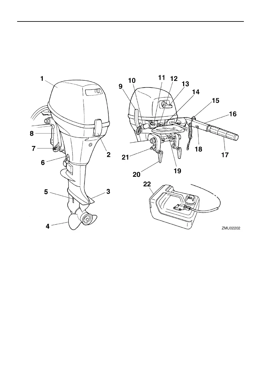
Components diagram
* May not be exactly as shown; also may not be included as standard equipment on all models
(order from dealer).
F8CMH
1. Top cowling
2. Cowling lock lever
3. Anti-cavitation plate
4. Propeller
5. Cooling water inlet
6. Drain screw
7. Trim rod
8. Clamp bracket
9. Gear shift lever
10.Flushing device
11.Choke knob
12.Fuel joint
13.Manual starter handle
14.Alert indicator
15.Engine stop button/Engine shut-off switch
16.Tiller handle
17.Throttle grip
18.Throttle friction adjuster
19.Tilt lock lever
20.Clamp screw
21.Restraint cable attachment
22.Fuel tank
U60R79E0.book Page 16 Wednesday, December 18, 2013 1:32 PM