[3A]
[3A]
[4A]
[3B]
[3B]
[6]
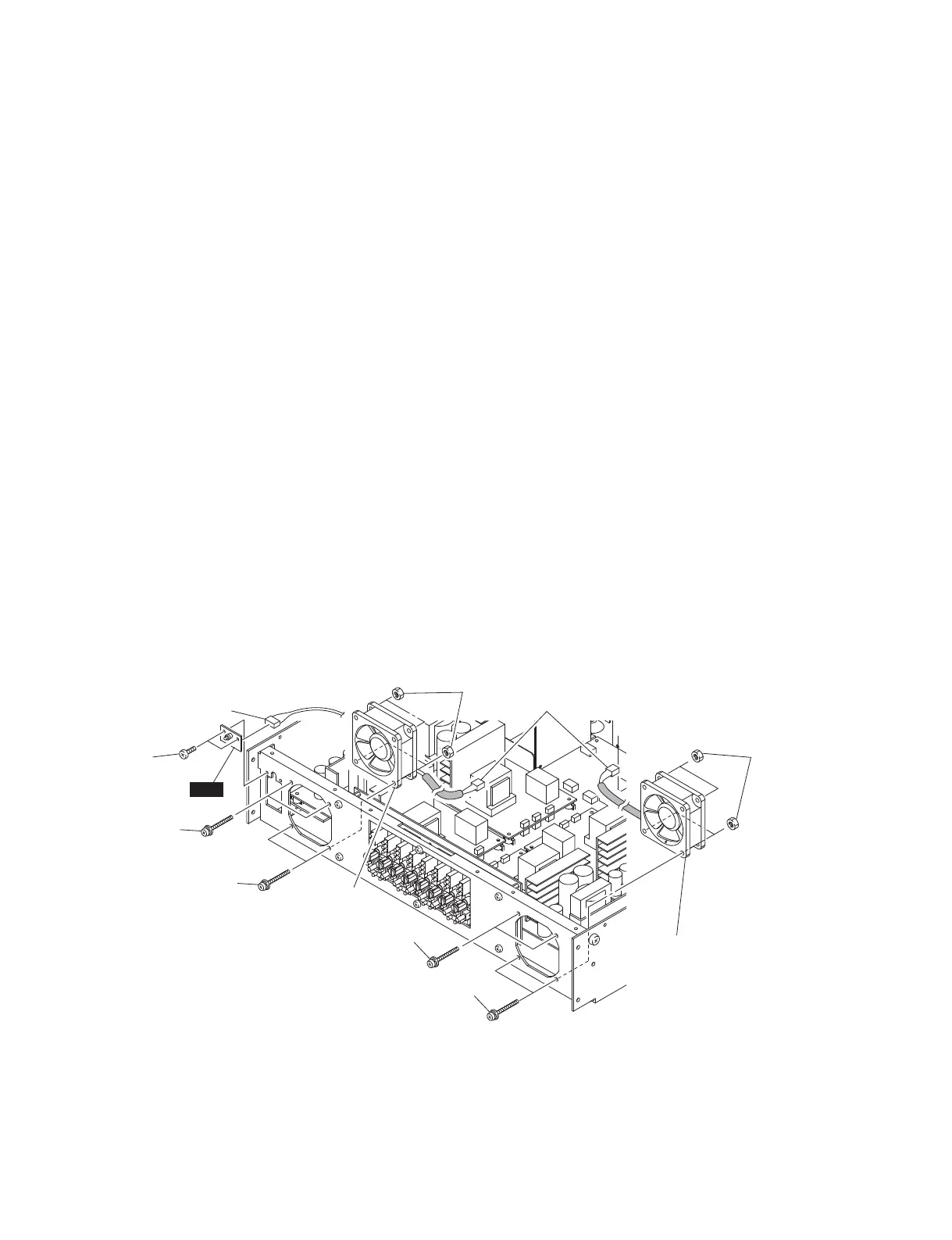
Left fan
左側のファン
Right fan
右側のファン
Connector assembly
束線
Connector assembly
束線
[4B]
LED
Fig. 10
(図 10)
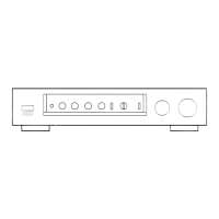
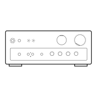
11. Fans (Time required: about 8 minutes)
11-1. Remove the top cover. (See procedure 1.)
11-2. Remove the front panel together with the deco panel
assembly and power switch assembly.
(See procedure 10.)
Left Fan
11-3. Disconnect the left fan connector assembly from the
INPUT POWER circuit board. (Fig. 10)
11-4. Remove the four (4) screws marked [3A] and four (4)
hexagonal nuts marked [4A]. The left fan can then be
removed. (Fig. 10)
Right Fan
11-5. Disconnect the right fan connector assembly from the
INPUT POWER circuit board. (Fig. 10)
11-6. Remove the four (4) screws marked [3B] and four (4)
hexagonal nuts marked [4B]. The right fan can then be
removed. (Fig. 10)
12. LED Circuit Board
(Time required: about 5 minutes)
12-1. Remove the top cover. (See procedure 1.)
12-2. Remove the front panel together with the deco panel
assembly and power switch assembly.
(See procedure 10.)
12-3. Remove the two (2) screws marked [6]. (Fig. 10)
12-4. Disconnect the connector assembly from the LED
circuit board. The LED circuit board can then be
removed. (Fig. 10)
11. ファン(所要時間:約 8 分)
11-1. トップカバーを外します。(1 項参照)
11-2. フロントパネルを DECO パネル Ass'y、電源スイッ
チ Ass'y と共に外します。(10 項参照)
左側のファン
11-3. 左側のファンの線材を INPUT シートから外します。
(図 10)
11-4.[3A]のネジ 4 本、[4A]の六角ナット 4 個を外し、
左側のファンを外します。(図 10)
右側のファン
11-5. 右側のファンの束線を INPUT シートから外します。
(図 10)
11-6.[3B]のネジ 4 本、[4B]の六角ナット 4 個を外し、
右側のファンを外します。(図 10)
12. LED シート
(所要時間:約 5 分)
12-1. トップカバーを外します。(1 項参照)
12-2. フロントパネルを DECO パネル Ass'y、電源スイッ
チ Ass'y と共に外します。(10 項参照)
12-3.[6]のネジ 2 本を外します。(図 10)
12-4. LED シートから束線を外し、LED シートを外します。
(図 10)
[3A]: PAN HEAD SCREW M4x35 CR3 BLACK (WS522200)
小ネジ+ PANSP
[3B]: PAN HEAD SCREW M4x35 CR3 BLACK (WS522200)
小ネジ+ PANSP
[4A]: HEXAGONAL NUT M4.0 CR3 (AAX61890)
フランジ付き六角ナット
[4B]: HEXAGONAL NUT M4.0 CR3 (AAX61890)
フランジ付き六角ナット
[6]: BIND HEAD TAPPING SCREW-B 3x8 MFZN2BL (WS522000)
B タイト+ BIND
IPA8200
20