21
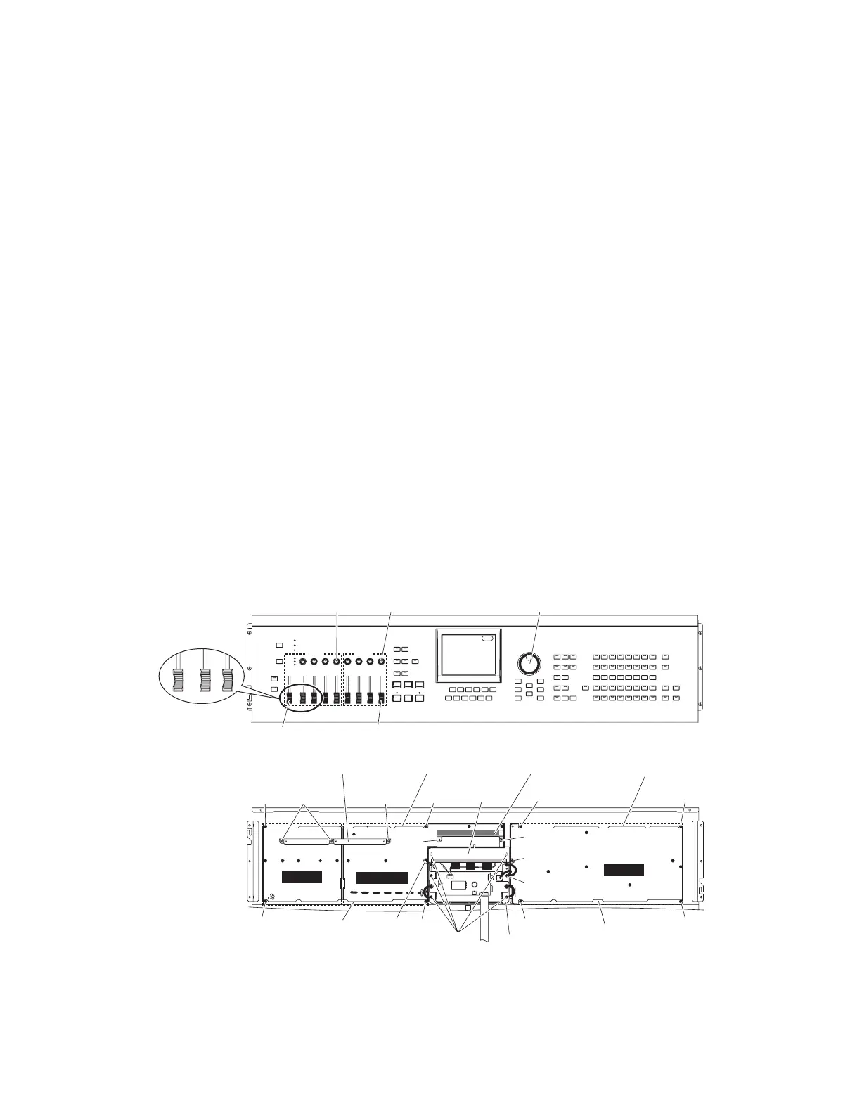
MOTIF XS6/MOTIF XS7/MOTIF XS8
<Top view>
<Bottom view>
A
B
Slider knob
(スライダーノブ)
Slider knob
(スライダーノブ)
Knob
(ノブ)
Knob
(ノブ)
Encoder knob
(エンコーダーツマミ)
PNA
PNC
PNB-PN
PCB angle 1 (A)
(PCBアングル1(A))
PCB angle 1 (A)
(PCBアングル1(A))
PCB angle 1 (B)
(PCBアングル1(B))
PCB angle 1 (B)
(PCBアングル1(B))
Shield plate JA
(シールド板JA)
[130A]
[70]
[70][40D] [110] [110]
[70] [410] [410]
[70]
[52B]
[52A]
[110]
[90A]
[130B]
[110]
Support angle
(サポートアングル)
EMC cover
(MCカバー)
Display assembly
(ディスプレイAssy)
* This fi gure shows the MOTIF XS6.(この図は MOTIFXS6 です。)
7. Display Assembly
(Time required: About 5 minutes)
7-1 Remove the side panel R and side panel L.
(See procedure 1.)
7-2 Remove the control panel assembly.
(See procedure 2.)
7-3 Remove the screw marked [40D], the screw
marked [52A] and the screw marked [90A]. The
EMC cover can then be removed. (Fig. 7)
7-4 Remove the five (5) screws marked [130A] and
the screw marked [130B]. The display assembly
can then be removed. (Fig. 7)
8. JKAN-LC Circuit Board, LCD
8-1 Remove the side panel R and side panel L.
(See procedure 1.)
8-2 Remove the control panel assembly.
(See procedure 2.)
8-3 JKAN-LC Circuit Board
(Time required: About 4 minutes)
8-3-1 Remove the screw marked [D80]. The JKAN-LC
circuit board can then be removed. (Fig. 8)
8-4 LCD (Time required: About 5 minutes)
8-4-1 Remove the EMC cover. (See procedure 7-3)
8-4-2 Remove the four (4) screws marked [D60] and
the screw marked [130B]. The LCD can then be
removed together with the display angle. (Fig. 7, 8)
8-4-3 Remove the screw marked [D50]. The LCD can
then be removed from the display angle. (Fig. 8)
7. ディスプレイ Assy(所要時間:約 5 分)
7-1 サイドパネル R とサイドパネル L を外します。
(1 項参照)
7-2 コンパネ Assy を外します。(2 項参照)
7-3 [40D] のネ ジ 1 本 と [52A] の ネ ジ 1 本、[90A] の
ネジ 1 本を外して EMC カバーを外します。(図 7)
7-4 [130A] のネジ 5 本と [130B] のネジ 1 本を外して、
ディスプレイ Assy を外します。(図 7)
8. JKAN-LC シート、液晶ディスプレイ
8-1 サイドパネル R とサイドパネル L を外します。
(1 項参照)
8-2 コンパネ Assy を外します。(2 項参照)
8-3 JKAN-LC シート(所要時間:約 4 分)
8-3-1 [D80] のネジ 1 本を外して、JKAN-LC シートを外
します。(図 8)
8-4 液晶ディスプレイ(所要時間:約 5 分)
8-4-1 EMC カバーを外します。(7-3 項参照)
8-4-2 [D60] のネジ 4 本と [130B] のネジ 1 本を外して、
ディスプレイアングルごと液晶ディスプレイを外
します。(図 7、図 8)
8-4-3 [D50] のネジ 1 本を外して、ディスプレイアング
ルから液晶ディスプレイを外します。(図 8)
Fig.7( 図 7)
[40D]: BindHeadTappingScrew-B(B タイト+ BIND)3.0X6MFZN2W3(WE936300)
[52A],[52B]: BindHeadTappingScrew-B(B タイト+ BIND)3.0X8MFZN2W3(WE774300)
[70]: BindHeadTappingScrew-B(B タイト+ BIND)3.0X6MFZN2W3(WE936300)
[90A]: BindHeadTappingScrew-B(B タイト+ BIND)3.0X6MFZN2W3(WE936300)
[110]: BindHeadTappingScrew-B(B タイト+ BIND)3.0X6MFZN2W3(WE936300)
[130A],[130B]:BindHeadTappingScrew-B(B タイト+ BIND)3.0X8MFZN2W3(WE774300)
[410]: BindHeadTappingScrew-B(B タイト+ BIND)3.0X6MFZN2W3(WE936300)

 Loading...