Do you have a question about the Yamaha PSR-E343 and is the answer not in the manual?
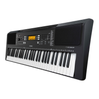
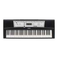
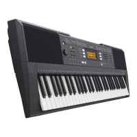
| Keyboard | 61 keys |
|---|---|
| Display | LCD |
| Amplifiers | 2.5W + 2.5W |
| Speakers | 12cm x 2 |
| Polyphony | 32 |
| Voices | 550 voices |
| Styles | 136 |
| Songs | 102 |
| Dimensions | 945 x 118 x 368 mm |
| Weight | 4.4 kg |
| Connectivity | USB to Host |
| Effects | Reverb, Chorus |
| Power Supply | PA-130 or six AA size batteries |
Diagram and list of controls on the front panel of the keyboard.
Diagram and list of connection jacks and terminals on the rear panel.
Layout of components and wiring within the upper case assembly.
Layout of components and wiring within the lower key bed assembly.
Step-by-step instructions for removing the lower case assembly.
Instructions for removing the DMLCD circuit board.
Procedure for removing the LCD display module.
Instructions for removing PN, AM, and MVR circuit boards.
Procedure for removing the speakers from the unit.
Steps for disassembling and removing the speaker grille.
Procedure for removing the lower key bed assembly.
General procedure for disassembling the keyboard assembly.
Instructions for removing white and black keys from the keyboard.
Procedure for removing rubber contacts for the key mechanism.
Steps to remove the 61L-MK circuit board.
Steps to remove the 61H-MK circuit board.
Procedure for removing spring terminals (A, B, C, D).
Pin description for the NT3881DFG-01 LCD driver IC.
Pin description for the ML9040A-B01GA LCD driver IC.
Pin description for the SPLC780D1 LCD driver IC.
Pin description for the SWL01U CPU IC.
Component layout diagram for the DMLCD circuit board.
Component layout diagram for the AM circuit board.
Component layout diagram for the PN circuit board.
Component layout diagram for the MVR circuit board.
Component layout diagram for the 61H-MK circuit board.
Component layout diagram for the 61L-MK circuit board.
Troubleshooting guide for DMLCD board based on symptoms and test points.
Required tools, jigs, and settings before starting the test program.
Procedure to boot the instrument into the test program mode.
How to navigate and execute tests within the test program.
List of test items, display messages, and judging criteria.
Settings that are automatically backed up and retained when power is off.
Methods for resetting settings to factory defaults (Backup Clear, Flash Clear).
Procedure to clear backed-up data from internal flash memory.
Procedure to clear transferred song/style files from memory.
List of abbreviations for destination models and regions.
Warning regarding replacement of critical components with equal specifications.
Exploded view and parts list for the overall assembly of the unit.
Exploded view and parts list for the upper case assembly.
Exploded view and parts list for the lower key bed assembly.
Exploded view and parts list for the 16NS keyboard assembly.
Detailed list of electrical components and their part numbers.