boss for the cam chain drive assembly shaft
(C). See Figure 48.
10. Install the cam chain drive assembly and the
cylinder head as described in Chapter Four.
11. Install the clutch as described in this chapter.
Inspection
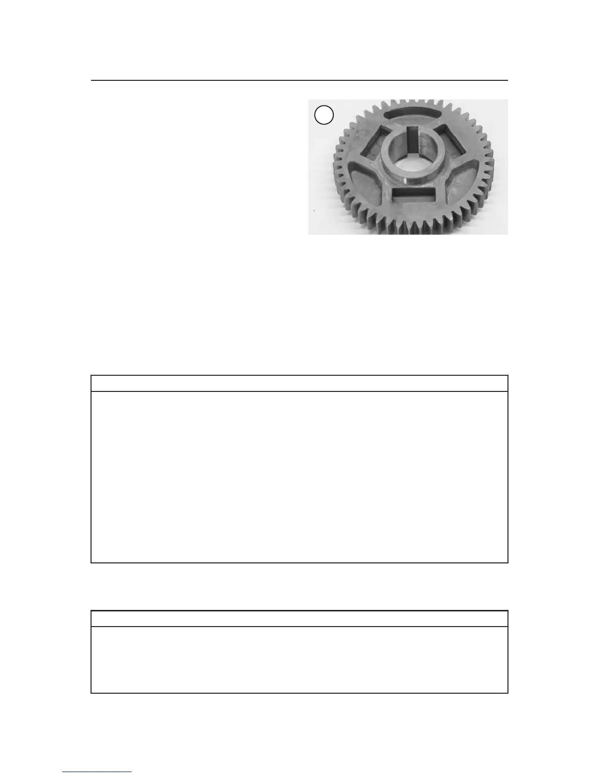
1. Inspect the primary drive gear (Figure 60) for
broken or missing teeth. If it is worn, replace the
primary drive gear and inspect the primary driven
gear on the clutch housing.
2. Inspect the dogs (A, Figure 57) and teeth (B) on
the timing gear for chips, cracks or other signs of
damage. If there is wear or damage, replace the tim
-
ing drive gear and inspect the front cylinder cam
chain drive assembly (Chapter Four).
3. Inspect the Woodruff key for nicks or other signs
of wear. If it is worn, replace the key and inspect the
keyway in the primary drive gear, timing gear, slot
-
ted washer and in the crankshaft.
4. Inspect the threads of the primary gear nut. Re
-
place the nut as necessary.
184 CHAPTER SIX
60
Table 1 CLUTCH SPECIFICATIONS
Item New mm (in.) Service limit mm (in.)
Friction disc
Thickness 2.9-3.1 (0.114-0.122) 2.8 (0.11)
Quantity 8 –
Clutch plate
Thickness 1.9-2.1 (0.075-0.083) 0.1 (0.004)
Quantity 7
Warp – Less than 0.1 mm (0.004 in.)
Clutch plate No. 1
Thickness 2.5-2.7 (0.098-0.106) 0.1 (0.004)
Quantity 1
Warp – Less than 0.1 mm (0.004 in.)
Clutch lever free play
At lever end 5-10 (0.20-0.39) –
Clutch spring free height 7.2 (0.283) 6.5 (0.256)
Clutch housing thrust clearance 0.05-0.40 (0.002-0.016) –
Clutch housing radial clearance 0.010-0.044 (0.0004-0.0017) –
Push rod No. 2 warp – 0.5 (0.02)
Table 2 CLUTCH AND PRIMARY DRIVE TORQUE SPECIFICATIONS
Item N•m in.-lb. ft.-lb.
Clutch adjuster locknut 12 106 –
Clutch cover bolts 10 89 –
Clutch nut 70 – 52
Clutch spring bolts 8 71 –
Primary drive gear nut 110 – 81
Shift-lever clamp bolt 10 89 –
 Loading...