MACHINING PROGRAM 4
4-41
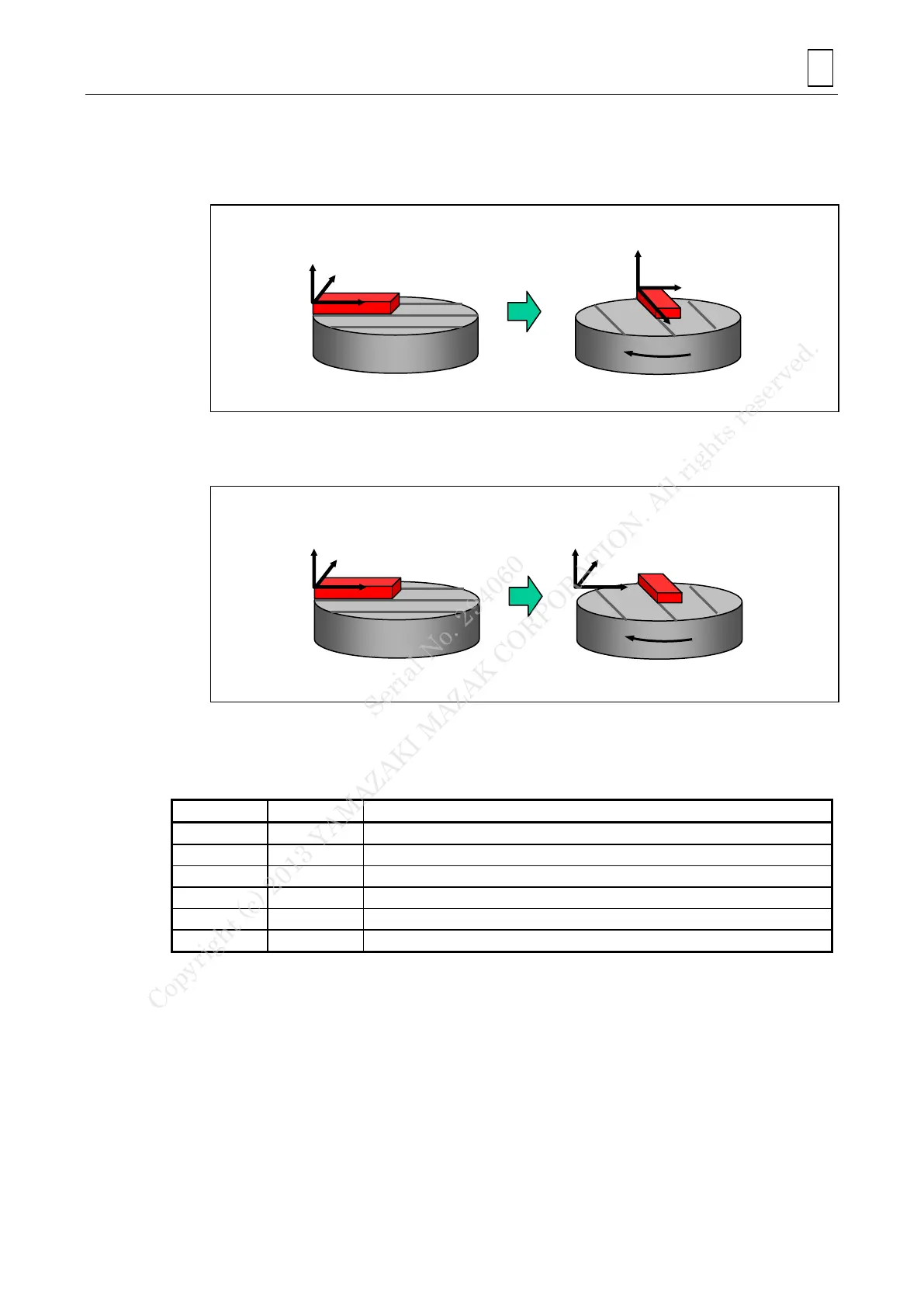
Note 2: Coordinate system for controlling the tool tip point is defined as follows.
The TABLE coordinate system (F85 bit 2: 0)
The table coordinate system will rotate as the table rotates.
But the tool axis rotation (e.g. the B axis for INTE) does not rotate the coordinate.
The WORK PIECE coordinate system (F85 bit 2: 1)
The current workpiece coordinate is the programming coordinate system which is fixed in
the orthogonal coordinate and does not rotate with the table.
D. G-codes/M-codes
See the document [99 Supplement] for details.
G-codes
High-speed machining mode OFF
High-speed machining mode ON
Tool tip point control (Type 1) ON
High-accuracy mode (Geometry compensation)
Note 1: The geometry compensation reduces geometry errors caused by the delay in the
smoothing circuits and servo systems.
Note 2: The high-speed machining mode features high-speed execution of free form programs
such as die and mold machining approximated by fine increments data.
Combined with the geometrical correction function, it produces high quality surface
finish.
Serial No. 294060
Copyright (c) 2013 YAMAZAKI MAZAK CORPORATION. All rights reserved.



 To Next Page