4 MACHINING PROGRAM
4-44
B. Program composition
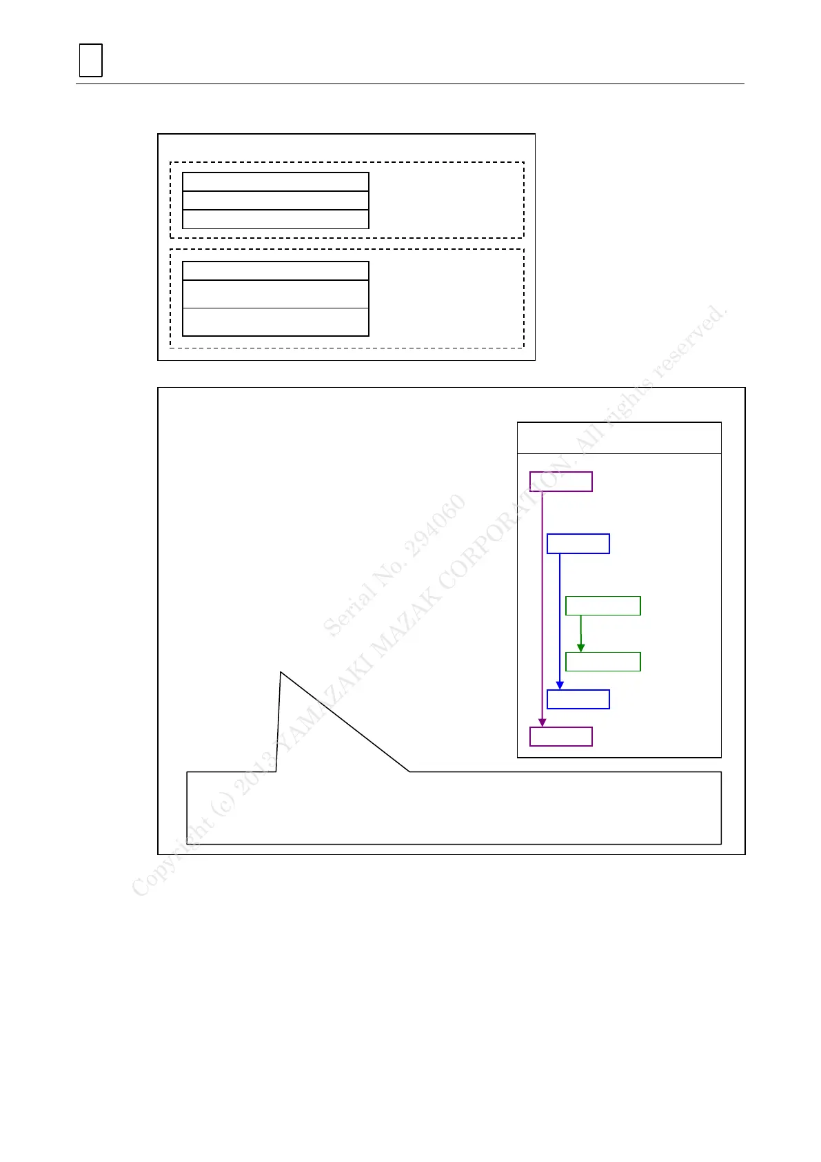
Machining motion of program composition
-Tool radius compensation for 5-axis machining-
G61.1
M108
G90G53Bb
G90G00Cc
G43.4G00XxYyZzBbCcHh
G41.5Dd
G01XxYyZzFf
(Machining pattern)
G0XxYyZz
G40
G49
G64
--- Geometry compensation ON
--- B-axis unclamping
--- B-axis positioning
--- C-axis positioning
--- Tool tip point control ON
--- Tool radius compensation for
5-axis machining
--- Head block for machining
contour F-code
--- Machining pattern
--- Escape
--- Tool radius compensation for
5-axis machining OFF
--- Tool tip point control OFF
--- Geometry compensation OFF
Tool radius compensation
for 5-axis machining
The figure below indicates setting of
each mode
Note 1: G43.4 should be commanded after the positioning of B and C axis, otherwise a large C axis motion
will cause unexpected motion.
Note 2: Giving a command for high-speed machining will lead to an alarm (807 ILLEGAL FORMAT) under
a combined use of tool radius compensation for five-axis machining with tool tip point control
(Reference: EIA manual 29-3-5.2)
Instruction in
machining motion
Instruction in
preparation motion
for machining
Tool radius compensation for
5-axis machining
Tool tip point control
Table coordinate system
Program composition element
Serial No. 294060
Copyright (c) 2013 YAMAZAKI MAZAK CORPORATION. All rights reserved.



 To Next Page