Chapter 9 Electrical System
4. Altemator
i 4LEIA
Series
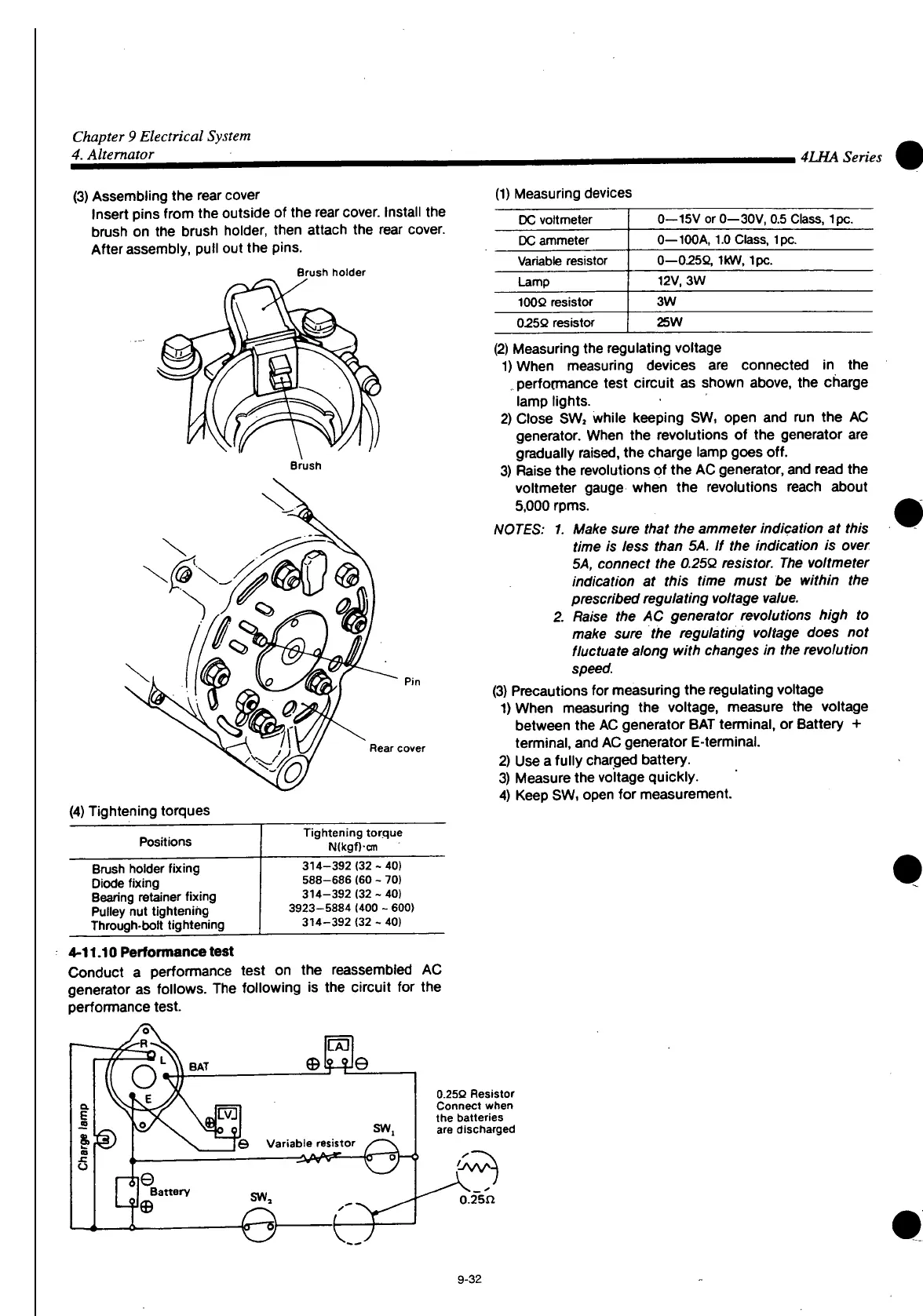
(3) Assembling the rear cover
Insert
pins
from
the outside of the rear
cover.
Install
the
brush on the brush holder, then attach the rear cover.
After
assembly,
pull out the pins.
(1) Measuring devices
Brush
holder
Rear
cover
(4) Tightening torques
Positions
Tightening torque
N(kgf)cm
Brush
holder fixing
Diode
fixing
Bearing
retainer fixing
Pulley
nut tightening
Through-bolt tightening
314-392
(32 - 40)
588-686 (60 - 70)
314-392
(32 - 40)
3923-5884 (400 - 600)
314-392
(32 - 40)
4-11.10
Performance
test
Conduct
a performance test on the reassembled AC
generator as follows. The following is the circuit for the
performance test.
DC
voltmeter
0—15V
or 0—30V, 0.5
Class,
Ipc.
DC
ammeter
0—100A,
1.0
Class,
Ipc.
Variable
resistor
0—0.25Q,
IkW, Ipc.
Lamp
12V,
3W
100Q
resistor
3W
025Q
resistor
25W
(2) Measuring the regulating voltage
1) When measuring devices are connected in the
performance test circuit as shown above, the charge
lamp lights.
2)
Close
SW, while keeping SW, open and run the AC
generator. When the revolutions of the generator are
gradually
raised,
the charge lamp goes off.
3)
Raise
the revolutions of the AC generator, and read the
voltmeter gauge when the revolutions reach about
5,000 rpms.
NOTES: 1. Make sure that the ammeter indication at this
time is less than 5A. If the indication is over
5A, connect the 0.250 resistor. The voltmeter
indication at this time must be within the
prescribed regulating voltage value.
2. Raise the AC generator revolutions high to
make sure the regulating voltage does not
fluctuate along with changes in the revolution
speed.
(3) Precautions for measuring the regulating voltage
DWhen
measuring the voltage, measure the voltage
between the AC generator BAT terminal, or Battery +
terminal, and
AC
generator E-terminal.
2)
Use
a
fully
charged battery.
3) Measure the voltage quickly.
4)
Keep
SW,
open for measurement.
0.25Q
Resistor
Connect
when
the batteries
are discharged
0.25n
9-32
 Loading...


