5 Installation Procedure
18 YASK AWA E LEC TRI C TOBP C730600 37B 1000-Series Option PG-X3 Installation Manual
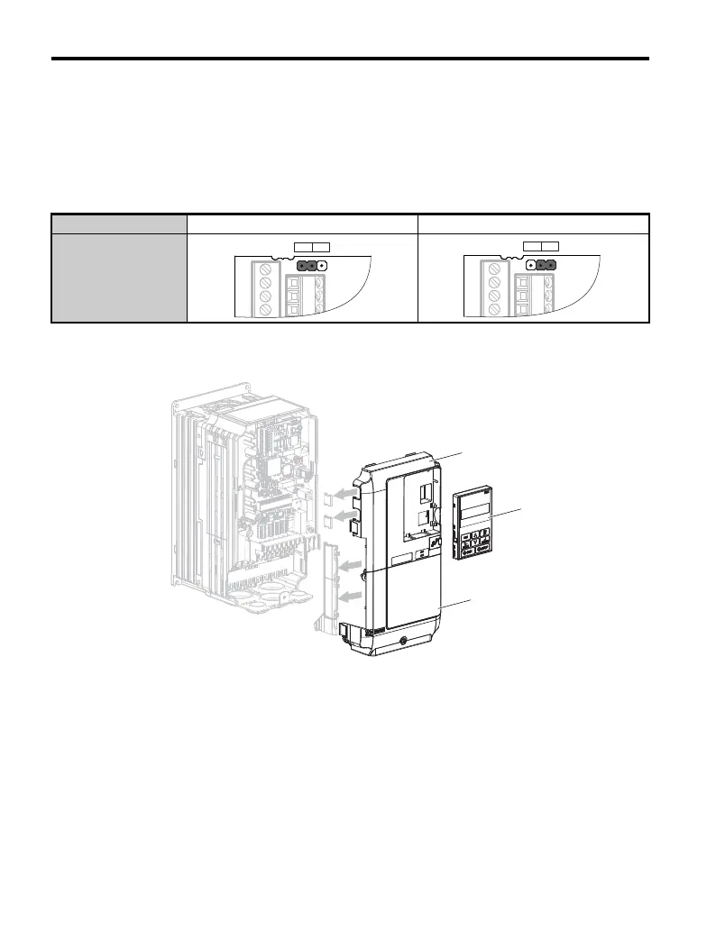
6. Set the voltage for the PG power supply using jumper CN3 located on the option.
Position the jumper as shown in Table 2 to select the voltage level.
NOTICE: The positioning of jumper CN3 selects the PG power supply voltage (5.5 V or 12 V). Select the
voltage level for the PG connected to the option and motor. If the wrong voltage is selected, the PG may not
operate properly or may become damaged as a result.
Table 2 Setting PG Power Supply Voltage (IP) with Jumper CN3
7. Replace and secure the front covers of the drive (D, F) and replace the digital
operator (E).
Figure 8
Figure 8 Replace the Front Covers and Digital Operator
Note: Take proper precautions when wiring the option so that the front covers will easily fit back onto
the drive. Make sure cables are not pinched between the front covers and the drive when
replacing the covers.
Voltage Level 5.5 V ± 5% (default) 12.0 V ± 5%
Jumper CN3
CN3
5.5 V 12 V

 Loading...


