5 Installation Procedure
YASKAWA ELECTRIC TOBP C730600 37B 1000-Series Option PG-X3 Installation Manual 19
8. Set drive parameters for proper motor rotation.
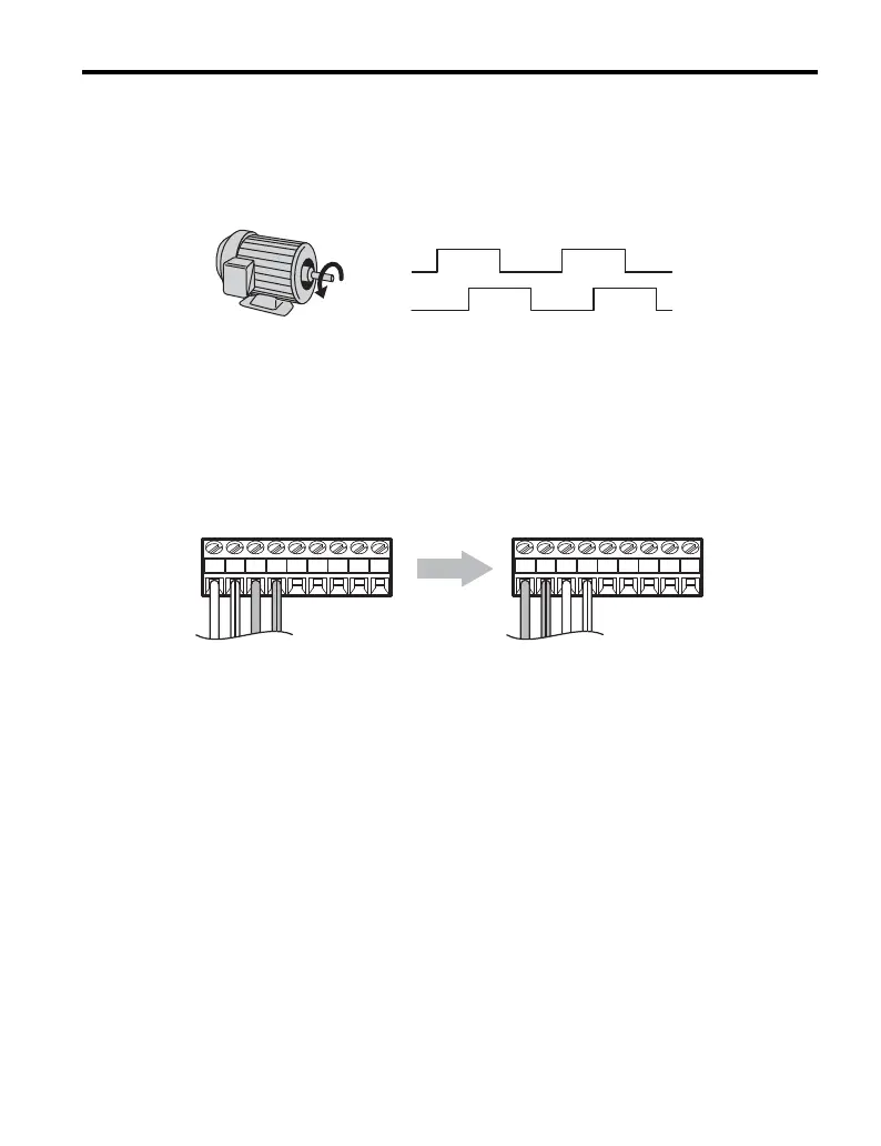
With a two-channel or three-channel encoder, the leading pulse determines the
motor rotation direction. A PG signal with leading A pulse is considered to be
rotating forward (counter-clockwise when viewing rotation from motor load side).
Figure 9
Figure 9 Displacement of A and B Pulses
After connecting the PG outputs to the option, apply power to the drive and
manually rotate the motor and check the rotation direction by viewing monitor U1-05
on the digital operator.
Reverse motor rotation is indicated by a negative value for U1-05; forward motor
rotation is indicated by a positive value.
If monitor U1-05 indicates that the forward direction is opposite of what is intended,
reverse the two A channel wires with the two B channel wires on option terminal
TB1 as shown in Figure 10.
Figure 10
Figure 10 A Channel and B Channel Wire Switching
If switching the wires is inconvenient, set drive parameter F1-05/F1-32 to 1 to switch
the direction of how the option reads pulses from the PG output.
Please note that when the drive is initialized using A1-03 =1110, 2220, 3330, the
value for F1-05/F1-32 will reset to factory default and the parameter will need to be
adjusted again to switch the direction.
A pulse
B pulse
The A pulse leads, followed
by the B pulse displaced at 90 degrees
Time
→
A+ B+A− B− Z+ SD FEZ− A+ B+A− B− Z+ SD FEZ−

 Loading...


