2 Spindle Orientation
YASKAWA TM.A1000SW.063 Spindle Orientation A1000 Custom Software Supplement 17
Function Description
The spindle orientation function begins when one of the orient digital inputs (80h, 81h, or 82h) outlined in Table 12 is
closed. These orient digital inputs can be broken into two modes: Orient from Run, and Orient from Stop. These two
modes are discussed later in this section.
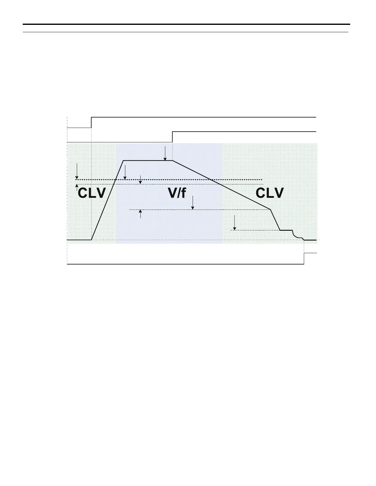
Orient only occurs when the drive is in Closed Loop Vector (CLV) control mode. This can be achieved by setting the P1-
02 Creep Speed below the window established by the S2-01 Control Mode Switchover Frequency and the S2-02 Control
mode Switchover Bandwidth. Figure 2 shows how the drive returns to Closed Loop Vector operation once an orient is
commanded.
Figure 2
Figure 2 Orient Operation with High Frequency Switchover
MachineSpeed
(Hz)
RunCommand
DecelTime
(C1-0X)
OrientSpeed
(P1-01)
CreepSpeed
(P1-02)
ORTDecTime
(P1-12)
FrequencyReference
(determinedbyb1-01)
OrientDigitalInput
(H1-0X=80/81/82h)
AccelTime
(C1-0X)
ControlModeSwitchover
Frequency(S2-01)
ControlModeSwitchover
Bandwidth(S2-02)
OrientComplete
(H2-0X=40h)
Frequency[(S2-01)‒ (S2-02)]
mustbegreaterthanP1-01or
OPE12errorwilloccur.

 Loading...


