2 Spindle Orientation
18 YASKAWA TM.A1000SW.063 Spindle Orientation A1000 Custom Software Supplement
Orient from Run
An Orient from Run is initiated by closing one of the orient digital inputs (80h, 81h, or 82h) while the drive is running.
These digital inputs command the drive to orient the spindle to the requested offset. In an orient from run, the drive soft
starter status is used to determine the orient direction. If the soft starter output is zero (the drive is holding position), the
orient direction is determined by the commanded run direction when an 80h Orient CMD is given, and by the orient
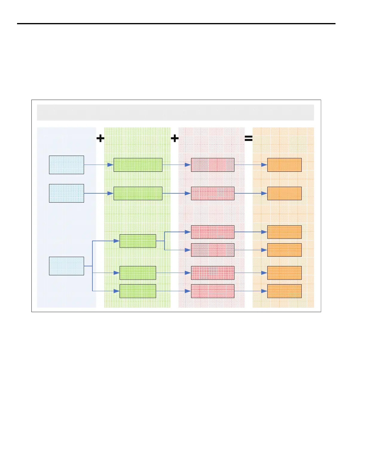
digital inputs themselves when an 81h Orient FWD or 82h Orient REV is commanded. The run direction logic is outlined
in Figure 3.
Figure 3
Figure 3 Orient Direction Determination
Both the run command and an orient digital input must be present for the drive to regulate and hold the desired position.
The 80h Orient Command digital input is special such that if the run command is removed during orientation, the drive
stops according to the b1-03 Stopping Method and orientation is not completed. Note, however, that the 81h Orient
Command Forward and 82h Orient Command Reverse digital inputs provide their own run command to the drive, so
removing the run command to the drive does not cancel the orient when using these orient digital inputs.
If the run command is present during orientation and all orientation digital inputs (80h, 81h, and 82h) are removed, the
drive resumes normal operation at the current speed reference.
When multiple orient digital inputs are issued simultaneously, the function of the subsequent orient digital inputs are
ignored. The orient command is cleared once all orientation digital inputs are opened.
Figure 4 covers the Orient from Run deceleration profile after an orient digital input is activated. The figure is broken up
into three areas. Area A includes deceleration to the P1-02 Creep Speed. Area B represents locating the marker.
Area C represents the final approach of the spindle once it has reached the desired offset. Each area is described in more
detail in the following sections.
DriveSFS
FWD
80/81/82hOrient
Command
80/81/82hOrient
Command
OrientFWD
OrientREV
80hOrient
CMD
81hOrient
CMDFWD
82hOrient
CMDREV
FWDRun
REVRun
OrientREV
OrientFWD
OrientFWD
OrientREV
DriveSFS
REV
DriveSFS
Zero
FWDorREV
FWDorREV
FWDorREV
FWDorREV
OrientDirection:OrientFromRun
RunDirection
(RunCommand+
FrequencyReference)
OrientDirectionOrientCommand
DriveSoftstarter
Polarity/Speed
(U1-02)

 Loading...


