2 Spindle Orientation
8 YASKAWA TM.A1000SW.063 Spindle Orientation A1000 Custom Software Supplement
Limitations
• The multi-function digital input function Motor 2 Select (H1- = 16) and Encoder Option Card Setting F1-30 have
restrictions when used in Closed Loop Vector control mode with an additional orientation encoder. Refer to Ta bl e 15 on
page 16 and Tab le 17 on page 31.
• Applications using Configuration 2 and Motor 1/Motor 2 switchover must use a motor encoder and an orientation
encoder of the same PPR.
• DriveWorks EZ functionality is not fully supported when using this software. If DriveWorks EZ support is required,
please contact Yaskawa Application Engineering.
• PG Encoder PPR parameters F1-01 and F1-31 are limited to PPR of 8 to 16384 PPR
(32 to 65536 counts per revolution).
• Orient functionality is disabled when the run command comes from the Local Operator (b1-02 = 0).
• Since all forms of speed search are disabled, the stopping method Coast to Stop (b1-03 = 1) causes inconsistent
operation of the spindle orient routine if an orient digital input is closed while the drive is coasting. This may include
but is not limited to overvoltage trips and faster than expected deceleration.
• Disabling reverse operation by setting Reverse Operation Selection parameter b1-04=1 prohibits the orient function
from maintaining position.
• Frequency Upper Limit parameter d2-01 prevents the spindle orient function from operating if the frequency limit is set
at or below the P1-02 Creep Speed.
• Orient digital inputs are disabled when Forward or Reverse Jog commands (H1-0 = 12 or 13) are active.
• Orient digital inputs are disabled when Control Mode Switchover Prevention digital input H1-0 = 50 is closed while
the drive is not running.
Related Parameters and Functions
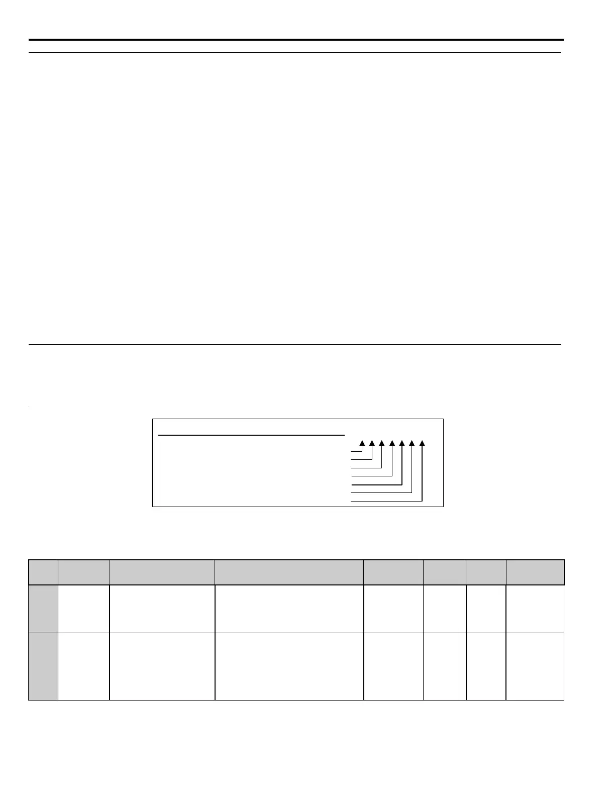
The legend below is used in this section to indicate which parameters are available in which control modes.
The parameter tables in this section are used to set up the drive for operation with the software.
Note: Chinese language support is added to certain parameters and functions. Refer to References on page 31 for the parameters and
functions with Chinese language support.
Table 3 Modified Parameters
No.
MEMOBUS/
Modbus
Address
Name
Digital Operator Display
Description Range
Default
Value
Change
During
Run
Control Method/
Access Level
F1-01 0380h
PG 1 Pulses Per Revolution
PG1 Pulses/Rev
Sets the number of encoder pulses per revolution
for the encoder on channel 1.
8 to 16384 PPR 1024 PPR No – – – Y– – N
F1-30 03AAh
PG Option Card Port for Motor 2
Selection
Mtr2 PG Port Sel
Specifies the drive port for the PG option card used
for Motor 2.
0: CN5-C
1: CN5-B
Note: This parameter is available without a digital
input H1-0 programmed to 16h (Motor 2 Select).
0 to 1 0 No – – – Y– – N
– – – Y – – Y
CLV/PM
OLV/PM
AOLV/PM
CLV
OLV
V/F w PG
V/f
N = Not Viewable
Y = Viewable/Available
–
= Not Available
Control Method / Access Level Decoding

 Loading...


