2 Spindle Orientation
YASKAWA TM.A1000SW.063 Spindle Orientation A1000 Custom Software Supplement 19
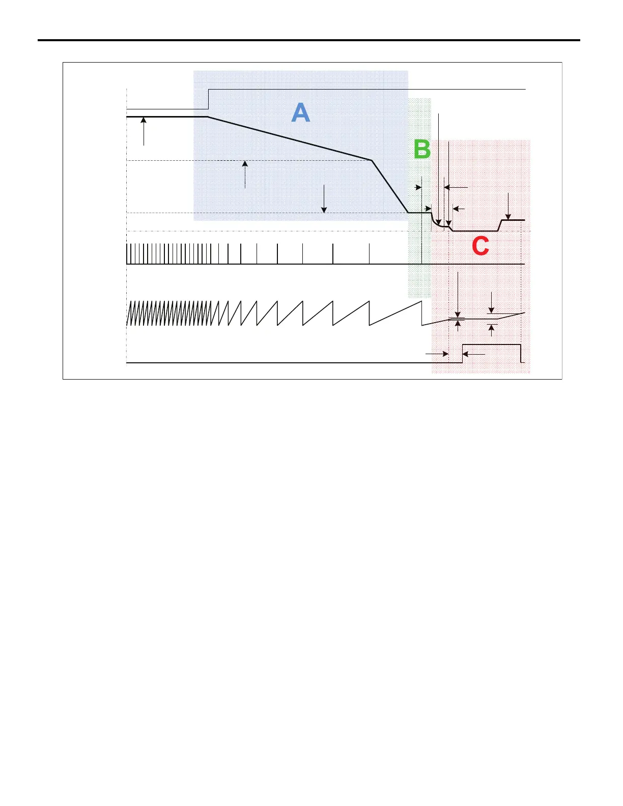
Figure 4
Figure 4 Orientation Deceleration Profile from Run
Area A: Deceleration
The drive decelerates using the C1-0 deceleration time until it reaches the Orient Speed defined in parameter P1-01.
At the P1-01 Orient Speed, the software checks the status of Orientation Deceleration Selection parameter P1-11 and
Orientation Deceleration Time parameter P1-12 to determine the deceleration time used at frequencies below P1-01.
If parameter P1-11 is enabled, deceleration time switches from C1-0 to P1-12 as shown in Figure 4 above. The drive
ramps its current ASR P Gain to ASR P Gain 3 (P2-10) if Orientation ASR Enable parameter P2-09 is enabled.
Area B: Marker Location
The P1-02 Creep Speed is the speed that the drive will cruise at while determining the location of the marker pulse on the
C/Z channel of the orientation encoder. The purpose of the Creep Speed is to provide a steady speed for reading the
marker pulse which gives consistent and repeatable marker pulse location. Once the marker pulse has been found, the
drive will disable s-curves and calculate the position error. The position error is calculated to be the distance between the
current spindle orientation and the selected P2-02/03/04/05 marker offset. If the position error is less than the number of
counts specified in Orientation Compensation Distance P1-09, the drive will add an additional rotation to allow the drive
to come to a controlled stop once the drive enters position error-based control.
Area C: Position Error-Based Control
The drive enters position error-based control once the calculated position error is less than the P1-03 Creep Distance.
Within the Creep Distance, the frequency reference is calculated using the product of the position error (in encoder
counts) and the Positioning Proportional Gain as determined by Positioning Proportional Gain parameter P1-08.
The frequency reference is upper limited to the P1-02 Creep Speed and lower limited to the P1-04 Approach Speed.
The purpose of the Approach Speed is to decrease the time it takes to complete an orient by ignoring low frequency
references until the drive reaches the P1-05 Orientation Complete Detection Set Window. If the P1-04 is programmed to
be greater than the P1-02, the drive runs at the P1-04 speed while within the creep distance. Within the creep distance, the
drive acceleration and deceleration times are also set to zero. This allows the drive to respond appropriately to the
position error without being influenced by the C1-0 accel/decel times.
ORTSetTime(P1-07)
OrientComplete
A/BPulseCount
(Equivalentto
ShaftAngle)
ZMarkerPulse
MachineSpeed
(Hz)
DecelTime
(C1-0X)
OrientSpeed
(P1-01)
CreepSpeed
(P1-02)
Rotationdueto
ExternalInfluence
ORTSetWindow
(P1-05)
ORTRstWindow
(P1-06)
(H2-0X=40h)
ORTDecTime
(P1-12)
FrequencyReference
(determinedbyb1-01)
OrientCompDist
(P1-09)
CreepDistance
(P1-03)
ApproachSpeed
(P1-04)
Position-Error×P1-08Gain
BasedSpeed
OrientDigitalInput
(H1-0X=80/81/82h)

 Loading...


