,din
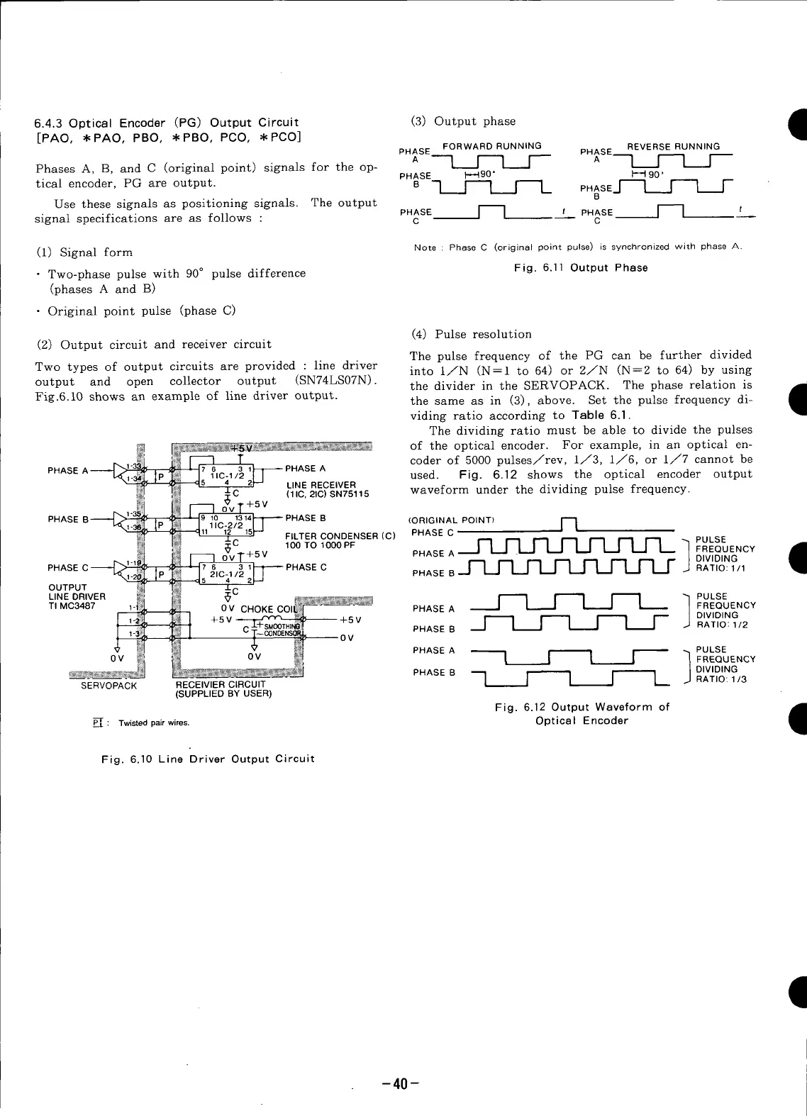
6.4.3 Optical Encoder (PG) Output Circuit (3) Output phase •
[PAO, * PAO, PBO, *PBO, PCO, * PCO]
1
FORWARD RUNNING REVERSERUNNING
PHASE PHASE__
A L__F-q F- A 1 _ I
Phases A, B, and C (original point) signals for the op-
PHASE }-_490" l-_ 90"
tical eneoder, PG are output. B q [_ [mE PHASE_[--_ _ r-
Use these signals as positioning signals. The output s
PHASE I I , PHASE ] I '
signal specifications are as follows : c c --
(1) Signal form Note : Phase C (original point pulse) is synchronizedwith phase A.
• Two-phase pulse with 90° pulse difference Fig. 6.11 Output Phase
(phases A and B)
• Original point pulse (phase C)
(4) Pulse resolution
(2) Output circuit and receiver circuit
The pulse frequency of the PG can be further divided
Two types of output circuits are provided : line driver into 1/N (N=I to 64) or 2/N (N=2 to 64) by using
output and open collector output (SN74LS07N). the divider in the SERVOPACK. The phase relation is
Jm
Fig.6.10
shows
example
of
line
driver
output.
an
the same as in (3), above. Set the pulse frequency di- •
viding ratio according to Table 6.l.
The dividing ratio must be able to divide the pulses
of the optical encoder. For example, in an optical en-
coder of 5000 pulses/rev, 1/3, i/6, or I/7 cannot be
PHASE A
used. Fig. 6.12 shows the optical encoder output
LINE RECEIVER waveform under the dividing pulse frequency.
:C (11C,21C)SN75115
"+5V
PHASE -- PHASEB (ORIGINALPOINT)
FILTERCONDENSER(C) PHASEC_ I PULSE
100TO1000PF FREQUENCY
-+5V PHASEA DIVIDING
PHASE PHASE C PHASE B J_J_J_J_J_J_J_ RATIO:1/1
OUTPUT C
..NE0R,VER I----I I PULSE
TIMC3487 PHASEA FREQUENCY
DIVIDING
PHASEB_ I-----1 [--q I'-- RAT.O:,.2
PHASEA _ PULSE
0V ! _ F---- "_FREQUE.CY
J
DIVIDING
PHASE B q _ I--"1"1[I RATIO: 113
SERVOPACK REOE,V.E.C,ROU'T
(SUPPLIED BY USER)
Fig. 6.12 Output Waveform of
P_: Twistedpairwires. Optical Encoder
I
Fig. 6.10 Line Driver Output Circuit
-40-