Application and Overload Selections
6-5
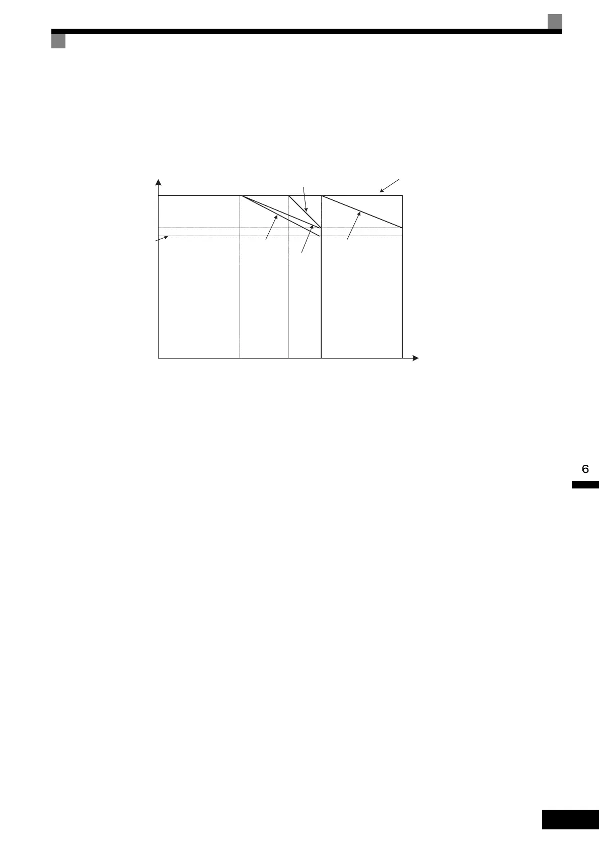
Carrier Frequency and Inverter Overload Current Level
When C6-01 is set to 1, the Inverter overload level will be reduced. Even when the overload current falls to
below 120% constant 1 min, OL2 (Inverter overload) will be detected. The Inverter overload current reduction
level is shown below.
Fig 6.2 Overload Current Reduction Level
100%
80%
5 kHz 10 kHz 15 kHz0
50%
8 kHz
75%
Overload current reduction level
Carrier frequency
200 V Class 30 kW
400 V Class 30 to 55 kW
200 V Class 22 kW or less
400 V Class 22 kW or less
200 V Class 37 to 90 kW
400 V Class 75 to 110 kW
400 V Class 132 kW
400 V Class 160 kW

 Loading...